Image processing method and inkjet recording apparatus

Active Publication Date: 2016-02-25
FUJIFILM CORP
View PDF5 Cites 15 Cited by
  • Summary
  • Abstract
  • Description
  • Claims
  • Application Information

AI Technical Summary

Benefits of technology

[0033]According to the present invention, it is possible to perform unevenness correction taking i

Problems solved by technology

Therefore, in a state where ink is undried or unfixed, it is difficult to accurately detect a difference in the ink amoun

Method used


Image

  • Image processing method and inkjet recording apparatus
  • Image processing method and inkjet recording apparatus
  • Image processing method and inkjet recording apparatus

Examples


first embodiment

Configuration of Image Recording Apparatus

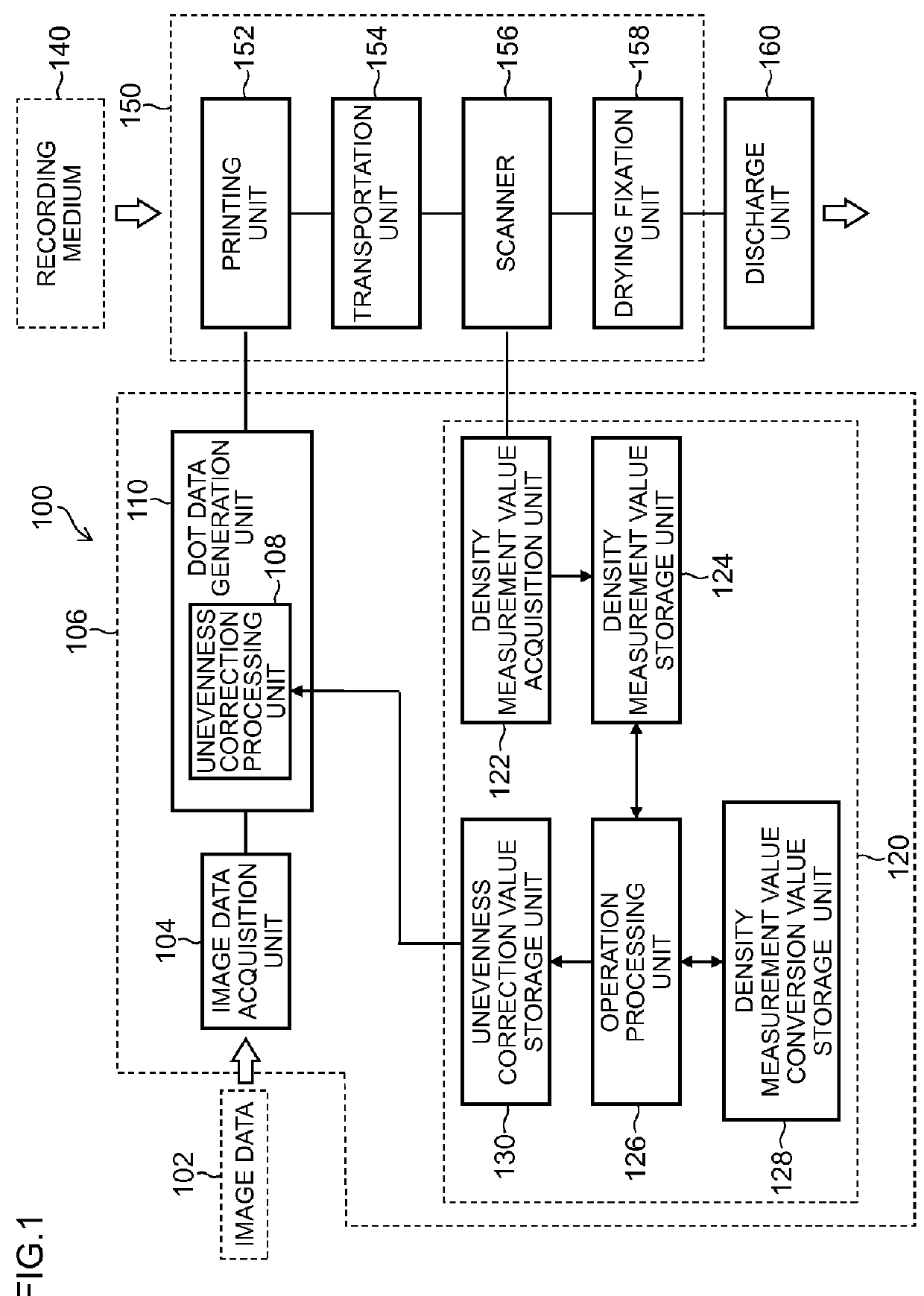
[0057]An inkjet recording apparatus 100 (one example of an image recording apparatus) illustrated in FIG. 1 is an inkjet printer of a single-pass method and includes an image data acquisition unit 104 that acquires image data 102 that is print image data showing a print image, a dot data generation unit 110 that generates dot data on the basis of input image data, and an image recording unit 150 that prints (records) an image on a recording medium 140 on the basis of the generated dot data.

[0058]The image data 102 is data of a raster format (raster data) for each color of RGB.

[0059]The image data acquisition unit 104 acquires the image data 102 through an input interface (not illustrated). Moreover, the image data 102 stored in a memory (not illustrated) such as a ROM (Read Only Memory) beforehand may be read out and acquired.

[0060]An image processing unit 106 (one example of an image processing apparatus) includes the dot data generation un...

second embodiment

Non-Ejection Correction and Density Conversion

[0120]In a case where a defective nozzle (non-ejection nozzle) that cannot eject ink is caused in an inkjet recording apparatus of a single-pass method, an image defect (stripe) is caused in a part corresponding to the nozzle in a printed image. Therefore, non-ejection correction is implemented to prevent the stripe from being caused. Various techniques have been suggested up to now as non-ejection correction, and, for example, there is adopted a method for covering a stripe part by a non-ejection nozzle by enlarging the dot diameter of ink ejected from a nozzle near the non-ejection nozzle.

[0121]FIG. 13A is a diagram microscopically illustrating the disposition of dots on a recording medium to which ink is deposited from each nozzle. In FIG. 13A, unevenness correction processing using the density measurement value conversion value of each nozzle is performed, and dots of the same size are uniformly disposed.

[0122]FIGS. 13B and 13C are d...

third embodiment

Light Quantity Difference Model

[0158]The nozzle-specific density measurement value conversion value of the first embodiment and the nozzle-specific anti-non-ejection correction unit density measurement value conversion value and nozzle-specific non-ejection correction unit density measurement value conversion value of the second embodiment are expressed by magnification=(density measurement value after drying fixation) / (density measurement value before drying fixation). However, if a strict model is considered, the relationship between a measurement density measurement value and a conversion density measurement value is not equivalent to simple magnification calculation.

[0159]When an unevenness correction value is assumed as V, a density measurement value before drying processing with respect to V is assumed as I_before and a density measurement value after drying processing is assumed as I_after, the relationship of both can be expressed as follows, using generally expressed transf...


PUM


Abstract

An image processing method includes: forming an image for density unevenness measurement on a recording medium in a single-pass method, using an inkjet head in which nozzles are disposed in a main scanning direction; acquiring a density measurement value of each set gradation value from an image for density unevenness measurement before drying; converting the acquired density measurement value into a conversion density measurement value corresponding to a post-dry density measurement value, using a density measurement value conversion value set for each region in the main scanning direction; and deriving a new unevenness correction value using this conversion density measurement value.

Description

CROSS-REFERENCE TO RELATED APPLICATIONS[0001]The present application claims priority under 35 U.S.C. §119 to Japanese Patent Application No. 2014-168521, filed on Aug. 21, 2014. The above application is hereby expressly incorporated by reference, in its entirety, into the present application.BACKGROUND OF THE INVENTION[0002]1. Field of the Invention[0003]The present invention relates to an image processing method and program, and an inkjet recording apparatus, and particularly relates to a technique that corrects density unevenness of an image to be recorded.[0004]2. Description of the Related Art[0005]As an image recording apparatus that records an image on a recording medium, there is known an inkjet recording apparatus that ejects ink from an inkjet head. For example, a configuration including the inkjet head corresponding to each color of C (cyan), magenta (M), yellow (Y) and black (K) is adopted.[0006]In an inkjet head, since there is dispersion in an ejection characteristic of...

Claims


Application Information

Patent Timeline
IPC IPC(8): B41J11/00
CPCB41J11/002B41J2/2142B41J2/2146H04N1/4015H04N1/6033H04N1/605B41J2/205B41J2/21B41J2/2132B41J2/2139B41J29/393B41J2029/3935
Inventor UESHIMA, MASASHI
Owner FUJIFILM CORP
Why Eureka
Try Eureka