Valve of a Hydraulically Striking Device

Active Publication Date: 2016-02-25
DOOFOR
View PDF1 Cites 4 Cited by
  • Summary
  • Abstract
  • Description
  • Claims
  • Application Information

AI Technical Summary

Benefits of technology

The valve of a hydraulically striking device described here has several advantages compared to previous designs. It stops leakage better because there is less surface area left on the second surface. The abutment surfaces are constructed in parallel relative to the end of the moving member, and the area towards which the moving member acts is bigger than with a sharp-edged construction of the moving member. This reduces the risk of damage to the moving member during operation and reduces the risk of jamming of the components of the hydraulically striking device.

Problems solved by technology

But in many of these valves, a common problem is that a sticking effect is created in the moving member when pressure of the hydraulic fluid is conducted inside the valve.
The surface that is towards the moving member is seldom even, which causes leakage and changes the pressure on that side.
This unwanted force can create the mentioned sticking effect.
Pressure from the pressure line leaks inside the valve and creates a force opening the moving member, which creates more leakage.
At first, this leakage is created because of the uneven surface of the sealing surface.
But this sharp edge is a problem in the hydraulically striking device because the moving member beats rapidly itself towards the housing of the valve, and this sharp edge does not last when the valve is used and in time will be worn off.
This type of a sharp edge will create metal chips into the hydraulic fluid when it is used, and metal chips can create malfunction in a hydraulic system for example by jamming the movement of moving parts inside the device.

Method used


Image

  • Valve of a Hydraulically Striking Device
  • Valve of a Hydraulically Striking Device
  • Valve of a Hydraulically Striking Device

Examples


Embodiment Construction

[0031]Reference will now be made in detail to the embodiments of the present invention, examples of which are illustrated in the accompanying drawings.

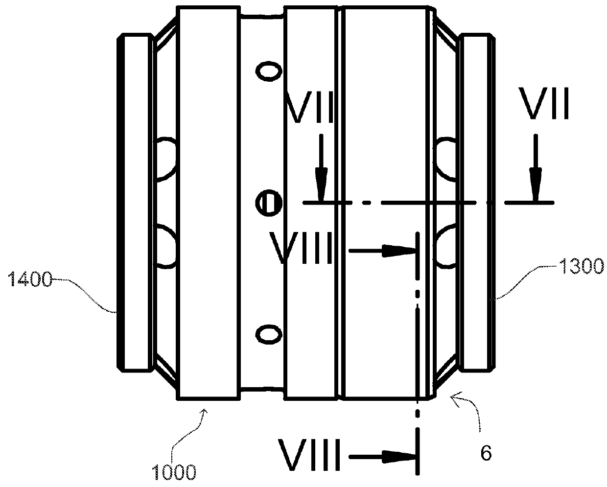
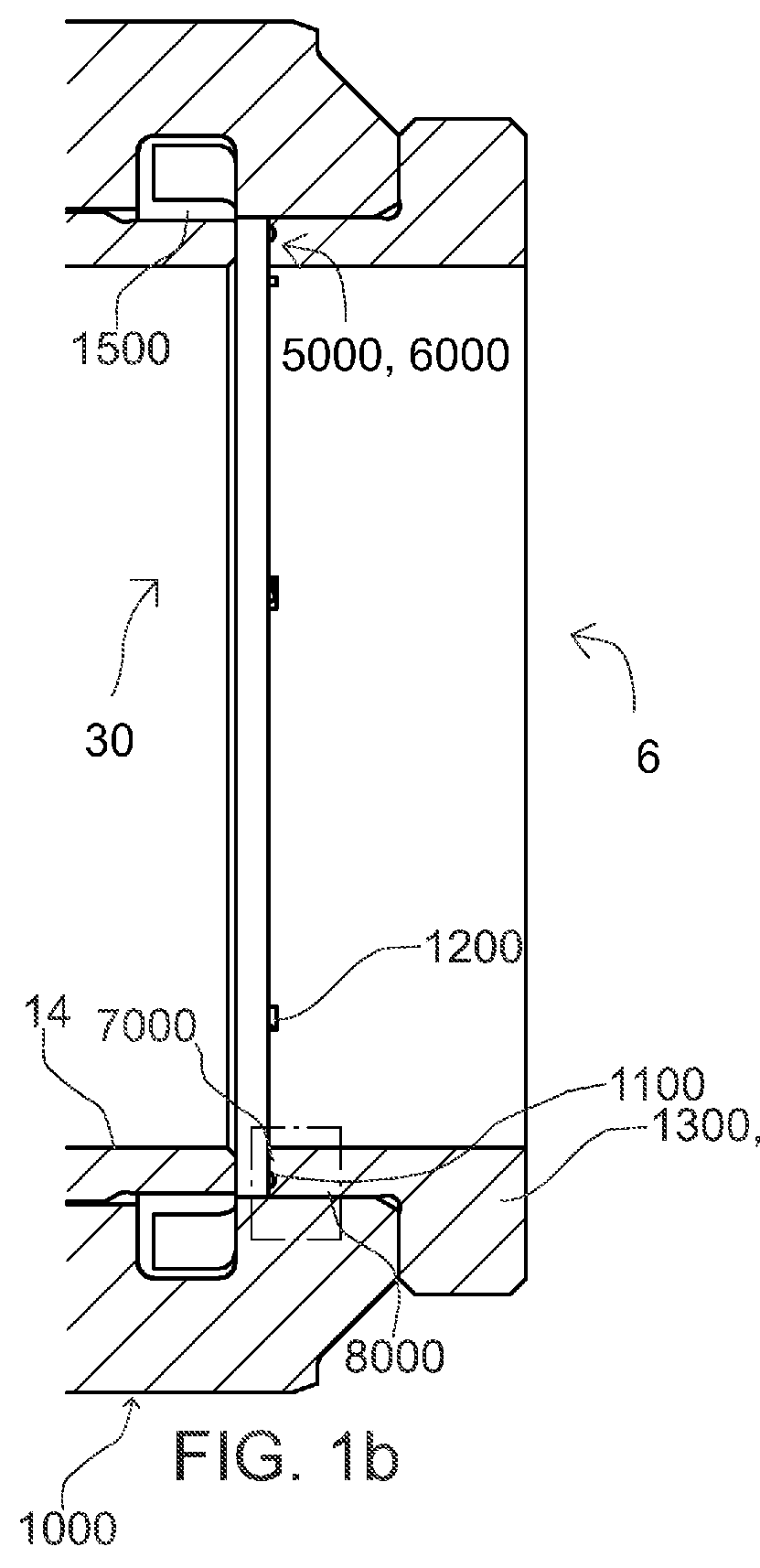
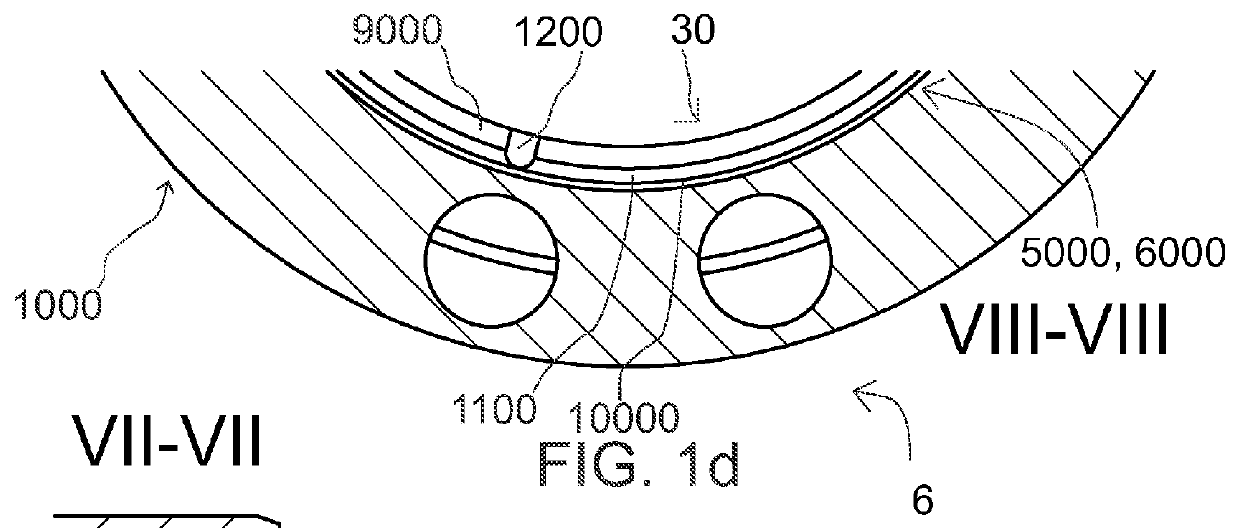
[0032]FIGS. 1a to 1d and 2a and 2b illustrate a valve 6 of a hydraulically striking device comprising a housing 1000, the housing 1000 comprising a moving member 14 being seated inside the housing 1000 to move in a reciprocating manner by means of a hydraulic fluid. As it is illustrated in FIGS. 1 and 2, the moving member 14 comprises an inner space 30, the housing 1000 comprises at least a first abutment surface 5000 abutting the moving member 14, the first abutment surface 5000 of the housing 1000 comprises a first surface 9000 located in a radial inner portion 7000 of the first abutment surface 5000, wherein the first surface 9000 is arranged in fluid communication with the inner space 30, and a second surface 10000 located in a radial outer portion 8000 of the first abutment surface 5000, wherein the second surface 10000 is arrang...


PUM

PropertyMeasurementUnit
Pressureaaaaaaaaaa

Abstract

A valve of a hydraulically striking device having a housing, the housing having a moving member being seated inside the housing to move in a reciprocating manner by means of a hydraulic fluid. The moving member has an inner space, the housing has at least a first abutment surface abutting the moving member, the first abutment surface of the housing has a first surface located in a radial inner portion of the first abutment surface, wherein the first surface is arranged in fluid communication with the inner space, and a second surface located in a radial outer portion of the first abutment surface, wherein the second surface is arranged to form a sealing surface.

Description

FIELD OF THE INVENTION[0001]The present invention relates to a valve of a hydraulically striking device and its components, and a method of manufacturing the valve, where the hydraulically striking device may be used for striking on a material hydraulically for example in rock drilling or similar applications.BACKGROUND OF THE INVENTION[0002]There are various types of valves for hydraulically striking devices on the market. Similar for many of these hydraulically striking devices may be that there is a piston that hydraulically reciprocates between a first position and a second position and that movement is controlled hydraulically with a controlling arrangement which is in connection with the device, which controlling arrangement may be a valve for example inside the device. This valve comprises a moving member or a similar type of device that moves back and forth inside the housing of the valve. The moving member controls the fluid flow that is needed for moving the piston. The va...

Claims


Application Information

Patent Timeline
IPC IPC(8): F16K27/04E21B1/00F16K3/02F16K31/12
CPCF16K27/04F16K3/0254E21B1/00F16K31/12F16K3/029E21B4/14B25D9/20E21B1/24
Inventor HAMALAINEN, JAAKKO
Owner DOOFOR
Why Eureka
Try Eureka