
Real time, automatic diagnostic system and method for electric networks

an automatic diagnostic and network technology, applied in the field of real-time, automatic diagnostic systems and methods for electric networks, can solve the problems of increasing the time of diagnostic and reaction, human error, and worsening the situation, so as to facilitate the construction of knowledge bases and reduce the need

Inactive Publication Date: 2016-02-25
COMPANY HIDRO ELECTRICA DO SAO FRANCISCO - CHESF
View PDF11 Cites 13 Cited by
  • Summary
  • Abstract
  • Description
  • Claims
  • Application Information

AI Technical Summary

Benefits of technology

The present invention is a method for automatically diagnostics and failures in power equipment using a combination of rules and models. The method reduces the need for updates and can be used with various equipment by using a small number of rules. It helps in identifying and addressing issues in the power grid in real-time, improving operational efficiency and preventing damage or downtime.

Problems solved by technology

The supervision and control centers of modern distribution and transmission of electric power have the complex task of managing large and geographically comprehensive grids.
However, the expert knowledge of human operators is still necessary to supervise the system and make critical decisions, especially in emergency situations.
In such situations, great amounts of events are usually generated (indicating potentially abnormal situations), a ripple effect often caused by a single failure.
The large volume of events in critical situations is a problem for system operation as it increases the time of diagnostic and reaction from operator, who have to “digest” all events outbreak to identify the real problems in the system.
In addition, humans are liable to make mistakes in stressful situations, and an incorrect diagnostic may worsen the situation even more once a wrong corrective action can damage equipment or propagate the effects of a localized failure to other parts of the system.
Apparently they have not considered the possibility of applying a technique or application developed for one type of network in other types.
Furthermore, another problem is an excessive number of rules to model a single problem.
However, that choice resulted in two major problems:The large number of rules needed to model the network problems;Constant maintenance due to changes in the grid topology.
With a base of 10,000 rules, this task becomes quite difficult, making impossible, in fact, the effective usage of such technique.

Method used


Image

  • Real time, automatic diagnostic system and method for electric networks
  • Real time, automatic diagnostic system and method for electric networks
  • Real time, automatic diagnostic system and method for electric networks

Examples


example 1

Disarming of a Transmission Line by Voltage Overload

[0391]The scenario consists of a disarming of a transmission line by voltage overload The line 04S9 interconnecting the facilities of RL and P will be used to illustrate the scenario. FIG. 18 and FIG. 19 present two terminals of transmission line. Flagged Events:[0392]14S9-PEN ABER[0393]1459-RLD ABER[0394]04S9-PEN STTT[0395]04S9-RLD STTT

[0396]After updating of events[0397]14S9-PEN ABER[0398]14S9-RLD ABER[0399]04S9-PEN STTT (event whose class of protection is overtension)[0400]04S9-RLD STTT (event whose class of protection is overtension)

[0401]After updating of connectivity state[0402]04S9-PEN not connected to energized equipment[0403]04S9-RLD not connected to energized equipment

[0404]Alarms generation:

[0405]Equipment of the topology that will be evaluated whose existence and activation conditions will be evaluated positively:

[0406]04S9-RLD / PEN[0407]Activated Rule: ‘LINE.TotalDisarmingLT’[0408]Alarm partially generated: $ID DISARMIN...

example 2

Failure of Circuit Breaker in an Installation of 230 kV

[0418]The scenario consists of a failure of circuit breaker in an installation of 230 kV shown in FIG. 20. The circuit breaker 14M1 located in the installation of R will be used to illustrate the failure. As a result of the failure, all circuit breakers associated to the busbar of 230 kV of the installation will open, generating the blackout in the installation.

[0419]Flagged Events:[0420]14M1-RIB FLDI[0421]04M1-RIB ATPR[0422]04M1-RCD ATPR[0423]04M1-RCD ATRB[0424]14M1-RCD ABER[0425]14M1-RCD FECH[0426]14M1-RCD ABER[0427]14S1-RIB ABER[0428]14T2-RIB ABER[0429]14T3-RIB ABER[0430]14T4-RIB ABER

[0431]After updating of the events:[0432]14M1-RIB failure of circuit breaker[0433]04M1-RIB actuation of protection (class of protection: DISTANCE)[0434]04M1-RCD actuation of protection (class of protection: DISTANCE)

[0435]After updating of connectivity state[0436]04M1-RCD Deenergized[0437]all equipment of Ribeirao were deenergized

[0438]Alarms gen...

example 3

Scenarios in an Electrical Grid

Scenario 1

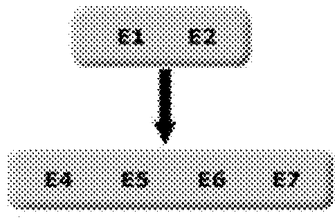
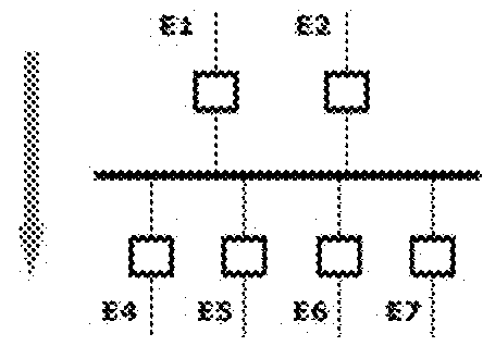
[0515]In the first step (Relations of topology / flow) it is possible to identify that the alarms lines from 1 to 7 depend on the transformers of alarms 8 and 9, and that the lines are equal to one another in relation to the flow, and the transformers as well. To this scenario, the graph which represents the energy flow between the elements is FIG. 7.

[0516]Suppose the filter stage needs to separate the alarms by diagnostic and by type de element, the resulting graph is the same because 8 and 9 have the same diagnostic e both are transformers, the same way 1, 2, 3, 4, 5, 6 e 7 gave the same diagnostic and all of them are lines.

[0517]To the validation of relation in the graph, the following propagation rule is used:[0518]To the relation Transformer→Line:[0519]If Transformer=‘disarming with actuation of protection of phase overcurrent then Line=‘Deenergized’.

[0520]With this rule (or some similar) it is possible to validate the model connection, ...


PUM


Abstract

A system and method for performing real-time and automatic diagnostics of failures in equipment located in an electrical grid, such as, for example, transmission and generation grids of electric power, using generic rules that consist in correlating events, especially applied in electrical grid with constant topology changes.

Description

STATEMENT OF RELATED APPLICATIONS[0001]This application claims the benefit of and is the US National Phase of International Application No. PCT / BR2014 / 000121 having an International Filing Date of 9 Apr. 2014, which claims priority on and the benefit of Brazilian Patent Application No. 10 2013 008594-4 having a filing date of 9 Apr. 2013.BACKGROUND OF THE INVENTION[0002]1. Technical Field[0003]The present invention is in the field of Electrical Engineering. More specifically, the present invention provides a system and method for performing real-time and automatic diagnostics of failures in equipment located in electrical grids such as, for example, transmission and generation grids of electric power. The system and method of the invention comprises the use of “generic rules” that harmonize the huge amounts of diagnostic points with the capabilities of systems, so as to provide event correlation, particularly applied to electrical grids with constant topology modifications.[0004]2. ...

Claims


Application Information

Patent Timeline
Patent Type & Authority Applications(United States)
IPC IPC(8): G01R31/00G01R31/08
CPCG01R31/003G01R31/088H04B3/46
Inventor MELO, MARIA DO SOCORRO CAVALCANTI DESAMPAIO, MARCUS COSTADUARTE, ALEXANDRE NOBREGANETO, ELOI ROCHASAUVE, JACQUES PHILIPPEFIGUEIREDO, JORGE CESAR ABRANTES DENICOLLETTI, PEDRO SERGIOPIRES, STEFANI SILVAFILHO, WALFREDO DA COSTA CIRNEARA JO, ANTONIO SERGIO DE
Owner COMPANY HIDRO ELECTRICA DO SAO FRANCISCO - CHESF
Features
  • Generate Ideas
  • Intellectual Property
  • Life Sciences
  • Materials
  • Tech Scout
  • Unparalleled Data Quality
  • Higher Quality Content
  • 60% Fewer Hallucinations
Learn More