Wear Protection Cap

a technology for wearing protection caps and hats, applied in the direction of rigid containers, manufacturing tools, transportation and packaging, etc., to achieve the effect of improving material flow and optimizing material flow

Active Publication Date: 2016-03-03
WIRTGEN GMBH
View PDF5 Cites 1 Cited by
  • Summary
  • Abstract
  • Description
  • Claims
  • Application Information

AI Technical Summary

Benefits of technology

[0019]According to a variant of the invention, provision can furthermore be made that a further panel segment configured as a top panel is adjacent to the front panel on the rear side in angled fashion, the top panel forming at least locally a convex discharge surface. Discharge of the milled material on both sides of the bit holder can be brought about via the convex surface region, thereby achieving optimized material flow toward the clearing and loading helix.
[0020]According to a variant of the invention, provision can also be made that two side panels arranged spaced

Problems solved by technology

In addition, the wear protection caps in the form of cast metal parts or forged metal parts allow for

Method used


Image

  • Wear Protection Cap
  • Wear Protection Cap
  • Wear Protection Cap

Examples


Embodiment Construction

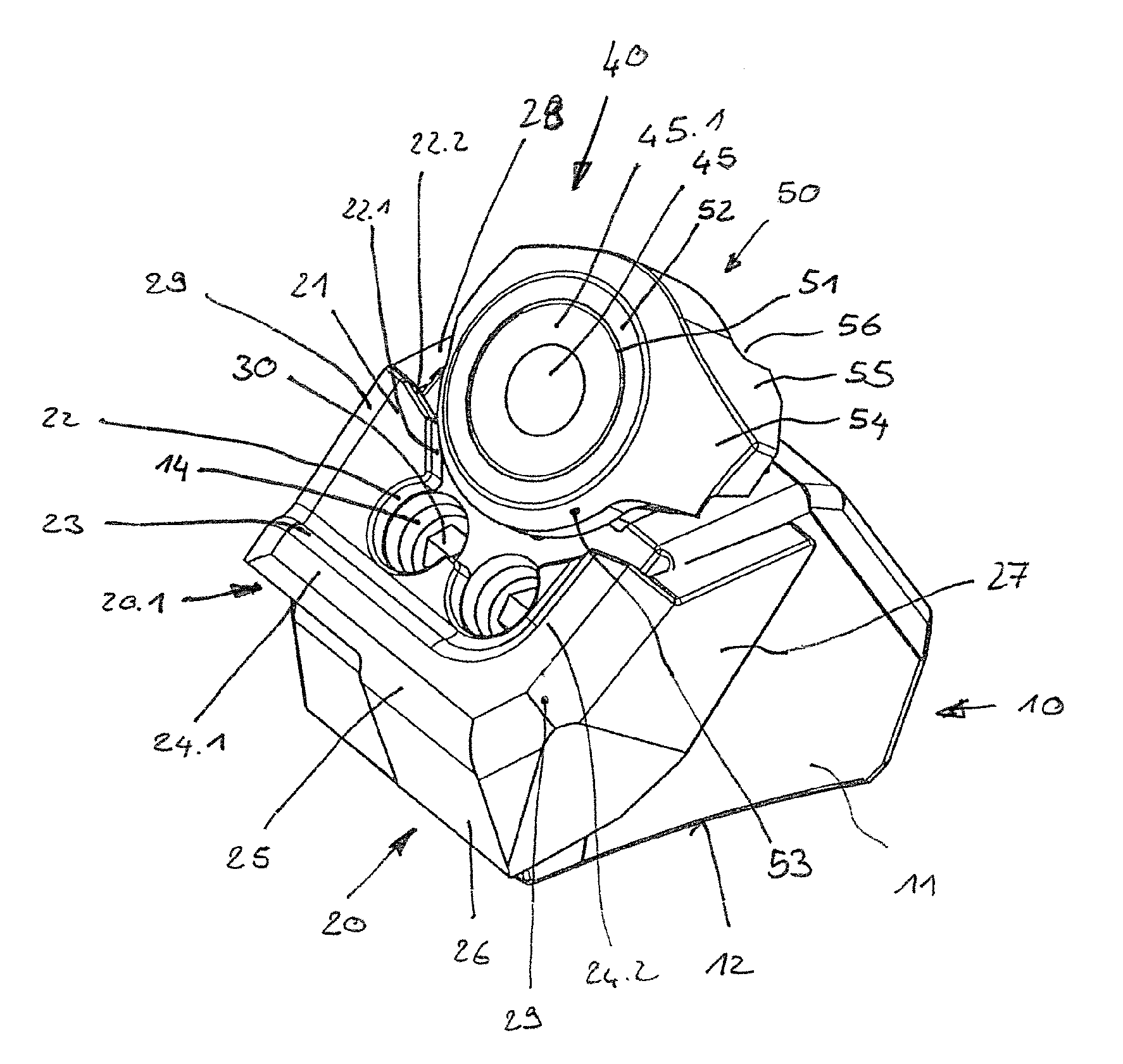
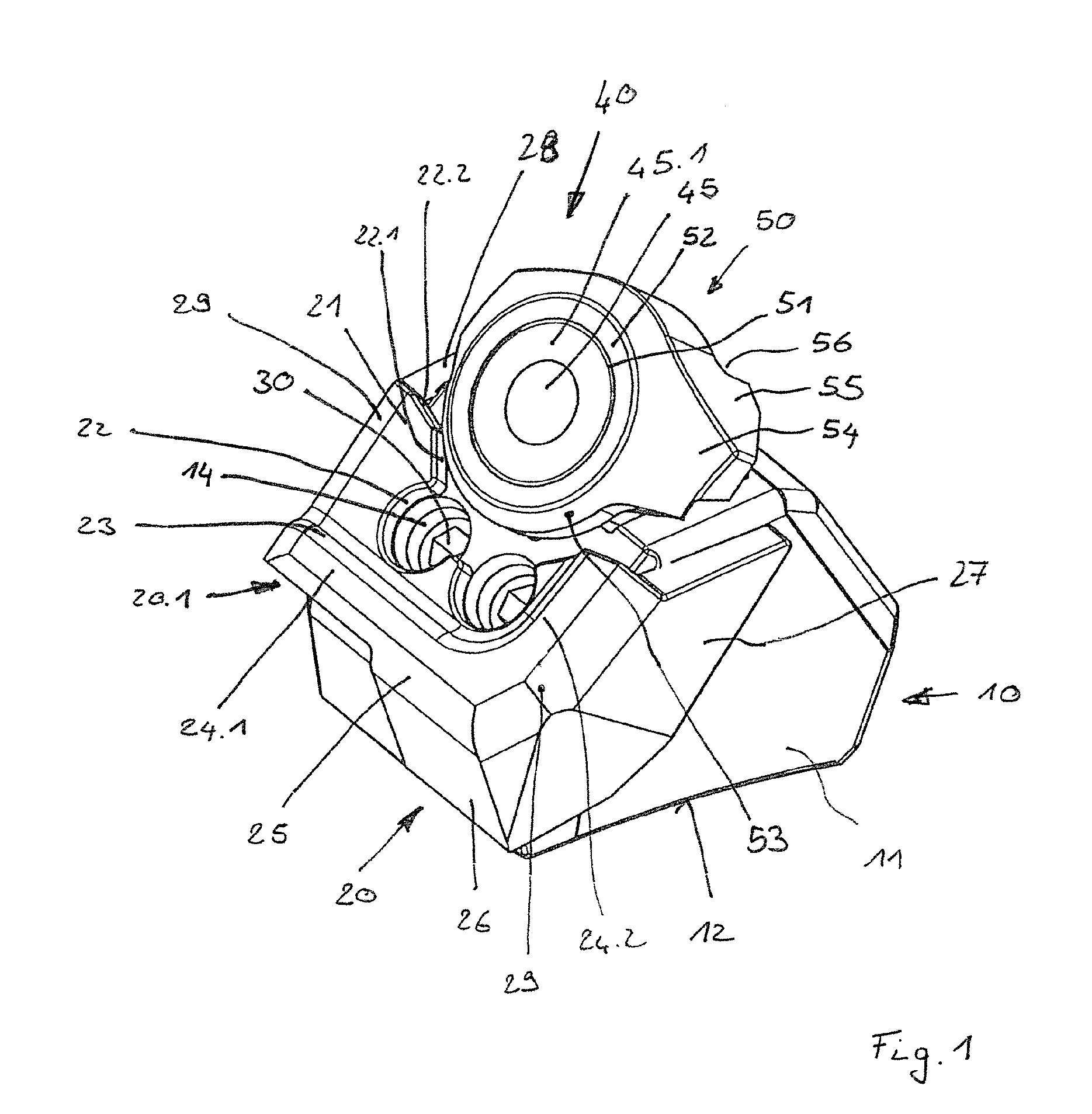
[0028]FIG. 1 shows a bit holder arrangement that is typically utilized in a surface miner. The bit holder arrangement comprises a base part 10 and a bit holder 40.

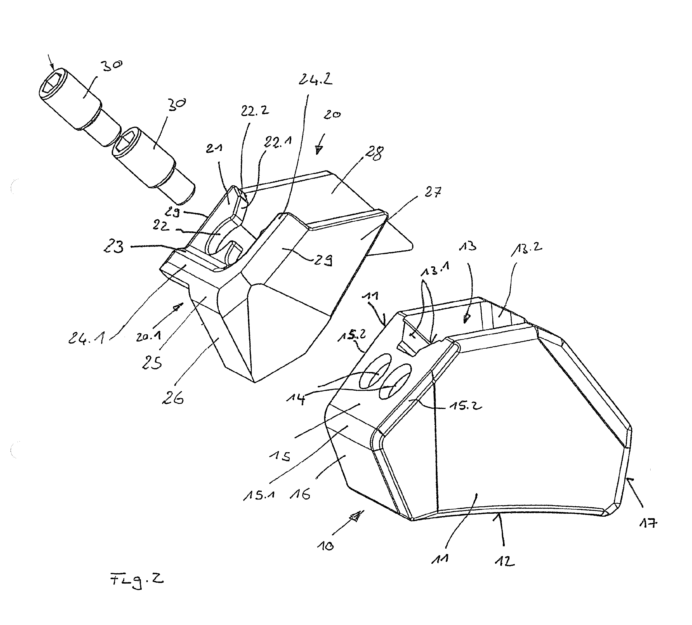
[0029]Base part 10 will be explained in further detail below with reference to FIG. 2. As depicted therein, base part 10 is configured in one piece and has two side parts 11. These are arranged spaced apart from one another. An insertion receptacle 13 is formed between side parts 11. In the region of its underside 12, base part 10 is provided with a concave surface. With this concave surface, base part 10 can be placed flush onto the surface of a tubular milling drum (not depicted). It can be secured there on the tubular milling drum with weld seams. Base part 10 has in the region of its front side, adjacently to side parts 11, a frontal projection. This projection is delimited at the front by a front surface 15 and by a further front surface 16. The two front surfaces 15 and 16 are located at an angle to one another and l...


PUM


Abstract

The invention relates to a wear protection cap for a bit holder arrangement, having at least two panel segments, located at an angle to one another, for covering surface regions of the bit holder arrangement, the panel segments being integrally joined to one another and the wear protection cap being configured as a cast metal part or as a forged metal part. With a wear protection cap of this kind, the service life of a bit holder arrangement can be substantially improved and machine stoppage time can be decreased.

Description

BACKGROUND OF THE INVENTION[0001]1. Field of the Invention[0002]The invention relates to a wear protection cap for a bit holder arrangement.[0003]2. Description of the Prior Art[0004]DE 10 2009 059 188 A1 (U.S. Pat. No. 8,746,806) discloses a bit holder arrangement. The latter encompasses a base part and a bit holder. The base part can be welded onto the outer surface of a tubular milling drum. The bit holder can then be replaceably fastened on the base part. A plurality of bit holder arrangements are secured on the surface of the tubular milling drum. They are preferably placed with respect to one another so that the base parts form a clearing and loading helix. A bit, preferably a rotatable round shank bit, can be replaceably received in the bit holder. The bit holder arrangements known from DE 10 2009 059 188 A1 are used in mining, preferably in open-cast mining. During processing use, the bits cut into the substrate that is to be removed, and detach material. The removed materia...

Claims


Application Information

Patent Timeline
IPC IPC(8): B25H3/00
CPCE21C35/18B25H3/003E21C35/183E21C35/1837
Inventor LEMMEY, PAUL, ANTHONYRONEY, BRETT, GEORGEMOORBY, JAMIE, SINCLAIR
Owner WIRTGEN GMBH
Why Eureka
Try Eureka