
Apparatus with variable compression ratio and variable expansion ratio

a technology of compression ratio and expansion ratio, which is applied in the field of internal combustion engines, can solve the problems of limiting the application of patents, difficulty in capturing the vcr and ver internal combustion engine technology, and no commercial engine has gone, and achieves low cost, large reduction ratio, and no adverse effects on the strength of the crankshaft

Active Publication Date: 2016-03-03
SHEN DAZI
View PDF3 Cites 10 Cited by
  • Summary
  • Abstract
  • Description
  • Claims
  • Application Information

AI Technical Summary

Benefits of technology

The present invention improves the performance of internal combustion engines and significantly reduces fuel consumption. It provides a good combustion environment in the cylinder chamber, regardless of application conditions, and reduces harmful emissions. The internal combustion engine can use different types of fuel without needing modifications. The apparatus of the invention uses a single drive system and is reliable and cost-effective. It also has a low power consumption and can be easily adjusted. Overall, the invention provides a practical solution for improving the performance of internal combustion engines.

Problems solved by technology

Despite of numerous inventions in the field, no commercialized engine has gone into the market, which implies the difficulty to capture the VCR and VER internal combustion engine technology.
Unfortunately, the apparatus in the patent can only be carried out in a single-cylinder engine, which limits the application of the patent.
In 1999, U.S. Pat. No. 5,927,236 to Gonzalez and other similar patents have the same or similar effects of the one to Clark, however, because either the strength of the crankshaft is greatly reduced or the set of driving mechanism is too complex, it is difficult to achieve reliable operation with low cost.
Thus, there is no practical use of the technology.
The apparatus in the patent is relatively simple, however, the planetary gear of the apparatus is placed in the main journal of the crankshaft, and in order to ensure the operation of the planetary gear, a huge space has been dug inside the main journal for placing the planetary gear, which greatly reduces the strength of the crankshaft.
At the same time, the diameters of the crankpin and the planetary gear are designed to be smaller because of the limitation of the structure, thus, it is difficult to improve the strength of the crankshaft by increasing the size.
In addition, the diameter of the ring gear is large while the meshing speed between the planetary gear and the ring gear is high, and the rigidity of the ring gear is insufficient, which impacts the NVH performance of internal combustion engine.

Method used


Image

  • Apparatus with variable compression ratio and variable expansion ratio
  • Apparatus with variable compression ratio and variable expansion ratio
  • Apparatus with variable compression ratio and variable expansion ratio

Examples


example 1

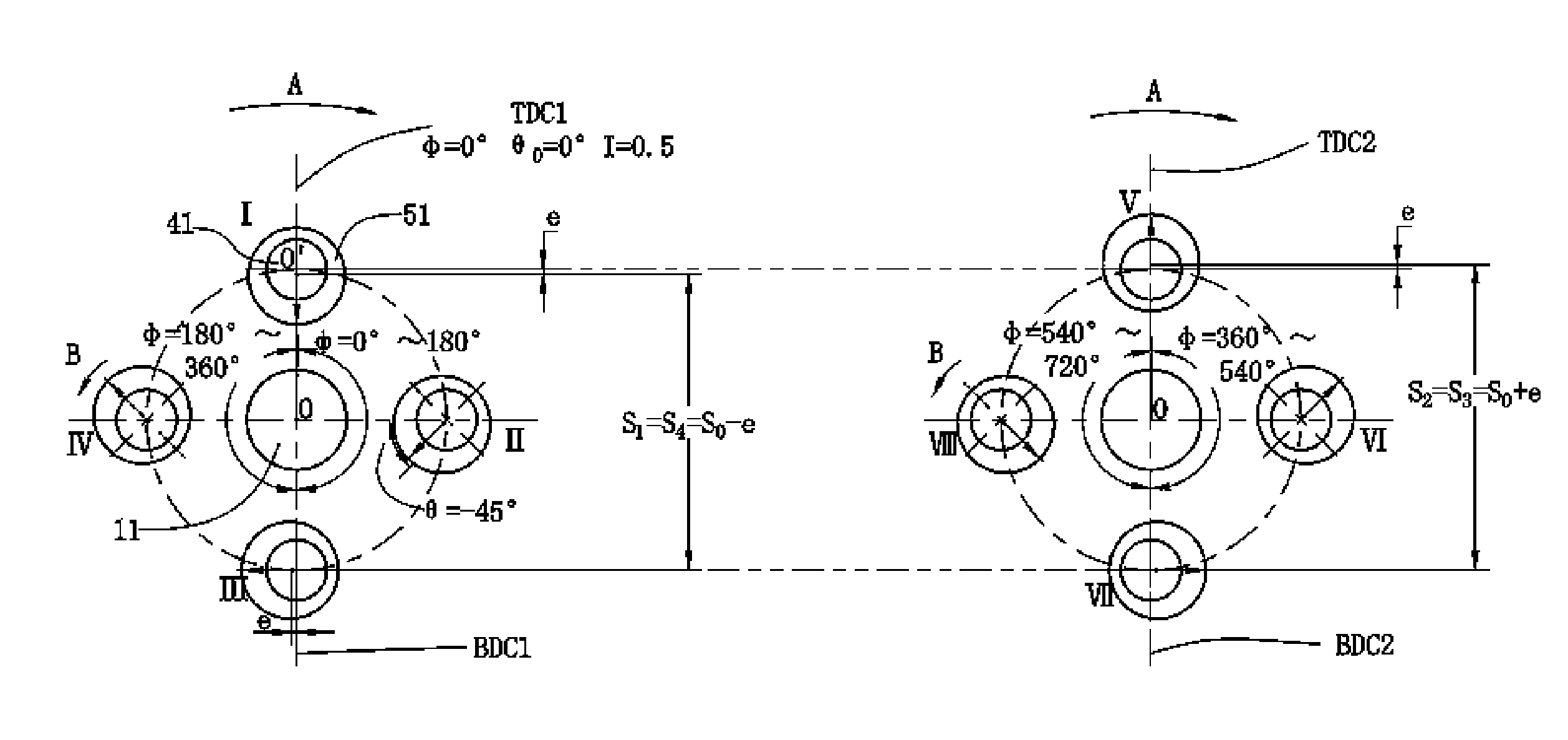
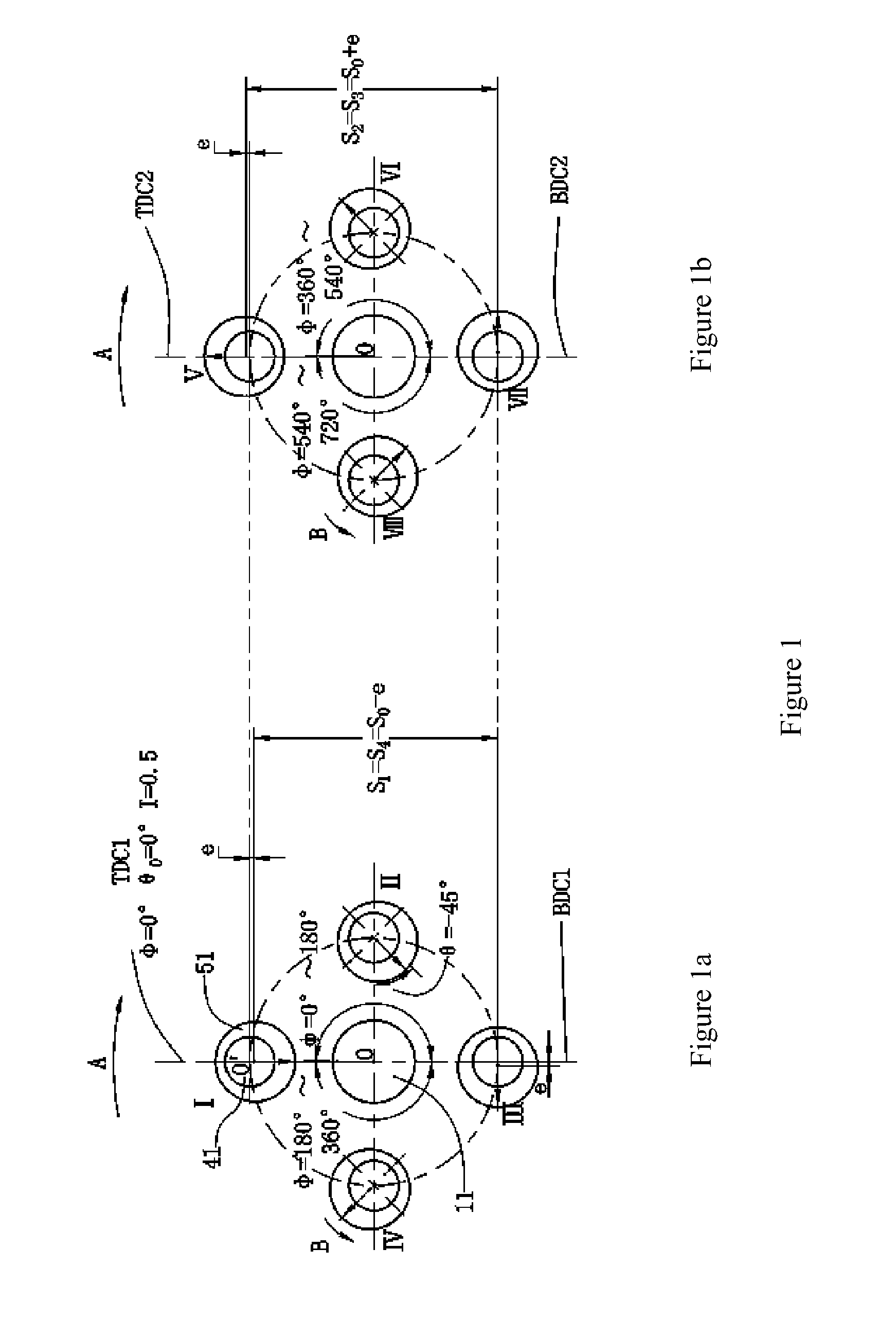
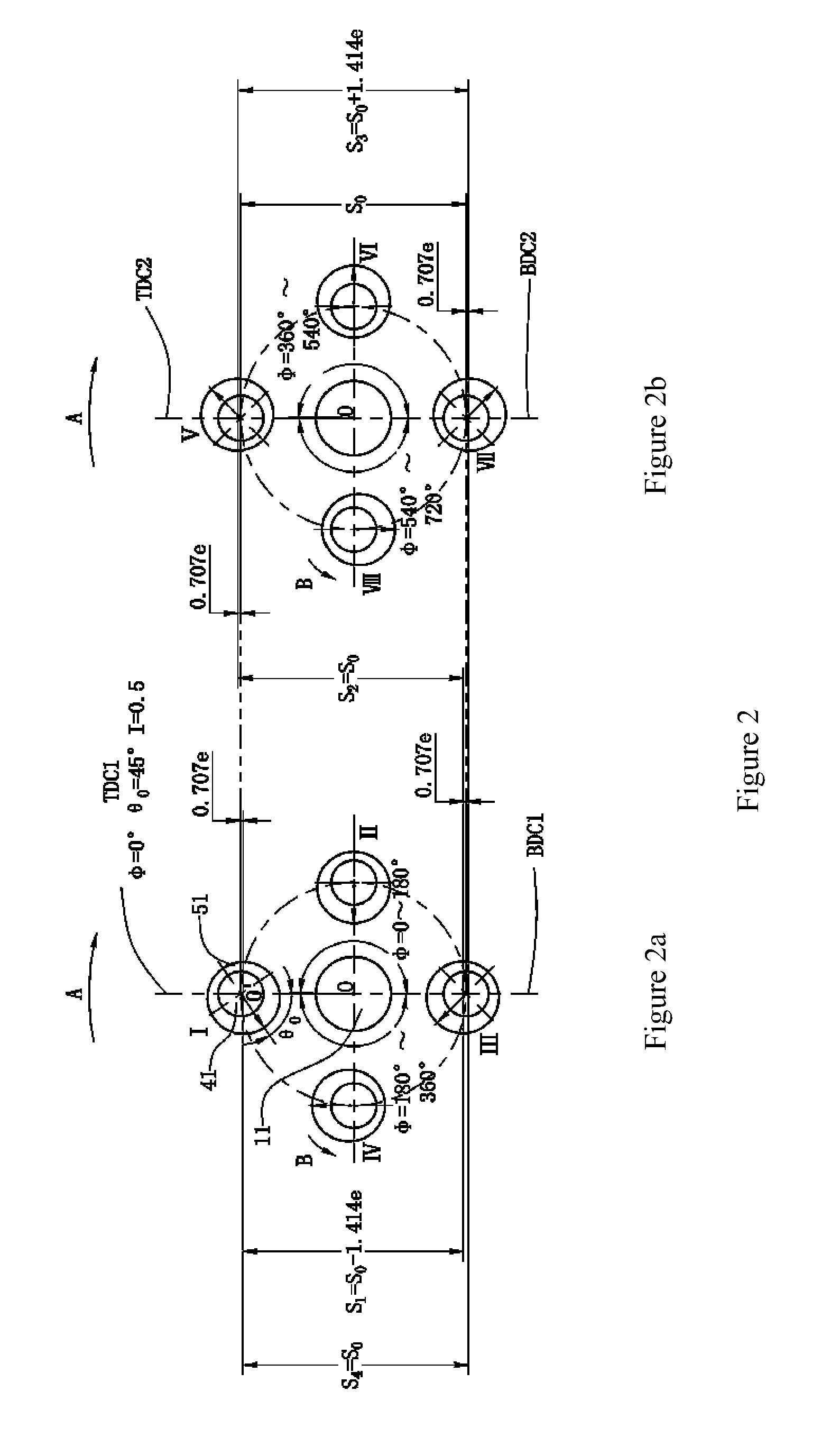
[0101]The example shows an embodiment of the present invention that is used for the four cylinder inline engine. Referring to FIGS. 6, 7, and 8, apparatus 200 with the variable expansion ratio and the variable expansion ratio is installed on the engine's crankshaft 100 and the assembly 5 of the piston connecting rod.

[0102]The assembly 5 of the piston-connecting rod is the traditional structure, it comprises piston, piston pin, connecting rod cap, connecting rod body and the big hole of the connecting rod, the piston is movably mounted within the cylinder of the internal combustion engine, the bearing bush were mounted in the big hole of the connecting rod

[0103]In order to set the eccentric sleeve on the crankpin, the crankshaft 100 adopts a split structure. The crankshaft 100 comprises the front main journal 10, the first main journal 11 and the plurality of other main journals one by one, the first crankpin 41 and the plurality of other crankpins of the following order and rear mai...

example 2

[0143]This example and embodiment is used for the four cylinder inline engine. As shown in FIGS. 11 and 12, the embodiment 2 has the same structure, transmission principle, function and role as Example 1 and embodiment 1 except for the following:

[0144]A) The axis 210 of the first transmission shaft, the axis 220 of the second transmission shaft, the axis 230 of the transmission shaft and axis 240 of the transmission shaft are all parallel with the axis 0-0 of the crankshaft 100, but do not coincide, that is: α=β4=β2=0.[0145]B) The transmission ratio I is 1:1, that is: I=(Z4 / Z31)*(Z32 / Z61)=1. In addition, in order to facilitate the transmission shafts through the main journals, make it from the front end of the main journals to reach the back end of the main journals, the diameters of the main journals are increased correspondingly.

example 3

[0146]This example and embodiment is used for the four cylinder inline engine. As shown in FIG. 13, the embodiment 3 has the same structure, transmission principle, function and role as Example 1 and embodiment 1 except for the following:

[0147]A) The axis 220 of the second transmission shaft, the axis 230 of the transmission shaft and axis 240 of the transmission shaft coincide with the axis 0-0 of the crankshaft 100.


PUM


Abstract

Apparatus with variable compression ratio and variable expansion ratio for an internal combustion engine, mounted on the engine crankshaft and the assembly of the piston-connecting rod, comprising an actuating motor, a worm, a worm gear, a sun gear, a first transmission shaft, a plurality of the transmission shafts, a first eccentric sleeve, a plurality of eccentric sleeve, a front gear of the first eccentric sleeve, a plurality of the front gear of the eccentric sleeve, a plurality of the rear gear of the eccentric sleeve, a planetary gear, the rear gear of the first transmission shaft, a plurality of the front gear of the transmission shaft, and a plurality of the rear gear of the transmission shaft. An angle α between the axis of the first transmission shaft and the axis of the crankshaft is not zero, the other axes of the transmission shafts with the axis of the crankshaft coincide, or parallel but do not coincide, or form a non zero angle.

Description

CROSS-REFERENCE TO RELATED APPLICATIONS[0001]The subject application is a continuation of PCT / CN2014 / 000072 filed on Jan. 20, 2014, which claims priority on Chinese patent application 201310182783.5 filed on May 16, 2013 in China. The contents and subject matter of the PCT and Chinese priority applications are incorporated herein by reference.TECHNICAL FIELD[0002]The present invention relates to the technical field of the internal combustion engine, particularly, an apparatus with variable compression ratio and variable expansion ratio for various reciprocating piston engines.BACKGROUND OF THE INVENTION[0003]It is well known that variable compression ratio (VCR) and variable expansion ratio (VER) for the internal combustion engine is a revolutionary technology with the most development potential in today's world. The technology plays a vital role to reduce carbon emissions, oil products, biofuels, and other fuel consumption. Despite of numerous inventions in the field, no commercial...

Claims


Application Information

Patent Timeline
Patent Type & Authority Applications(United States)
IPC IPC(8): F02B75/04F02D15/02
CPCF02D15/02F02B75/048Y02T10/12
Inventor SHEN, DAZI
Owner SHEN DAZI
Learn More