Display lighting system

a technology for lighting systems and displays, applied in the field of lighting systems, can solve the problems of affecting the appearance of the display, the difficulty of adjusting or modifying the system for a particular display layout, and the complexity of the display modification, so as to reduce the risk of electrical communication disruption, reduce the risk of orientation errors, and be rugged and reliable

Active Publication Date: 2016-03-03
AMSTORE
View PDF3 Cites 52 Cited by
  • Summary
  • Abstract
  • Description
  • Claims
  • Application Information

AI Technical Summary

Benefits of technology

[0007]In another embodiment, the low voltage power frame can include a frame indexing element, such as a slot or a ridge. This feature can be configured to register with a corresponding puck indexing element associated with the puck to ensure that the electrical connectors of the puck correctly match the first and second power rails, which can be of different polarities. Optionally, the puck indexing element can be offset laterally from a longitudinal axis of the puck so that the electrical connectors reduce orientation error and correctly position the puck.
[0008]In still another embodiment, the lighting array can include multiple lighting elements, and can be connected to a flexible electrical coupler. The electrical coupler can be electrically coupled to a power feed of the puck as well, enabling the puck and lighting array to be distal from one another to provide suitable placement of each. The coupler can transfer power from the puck to the light array to illuminate the lighting elements when the puck is joined with the low voltage frame via a magnetic force.
[0009]In yet another embodiment, the puck can include a puck body constructed from a molded polymeric material. The polymeric material can be molded over multiple components of the puck, such as a power feed and first and second puck electrical connectors, which optionally can be in the form of plates. The molded over material can enable the puck and its components to be rugged and reliable, with minimal risk of disrupting electrical communication between those components.

Problems solved by technology

In another example, the systems can be difficult to adjust or modify for a particular display layout.
In some cases, the light fixtures can be relatively heavy or cumbersome.
This can add complexity, time and expense to the modification of a display.
And even in cases where the light fixture may be rotatably mounted, the base of the fixture typically is only moveable in a single dimension, thereby limiting the degree of adjustability.
Many times, the structure of the track or display does not lend itself to such precise orientation, which can lead to an aesthetically displeasing display or unacceptable lighting characteristics.
Even further, the track can become marred or scratched upon repeated movement and reattachment of the light module.
This can lead to the display having an unsightly or damaged appearance.

Method used


Image

  • Display lighting system
  • Display lighting system
  • Display lighting system

Examples


Embodiment Construction

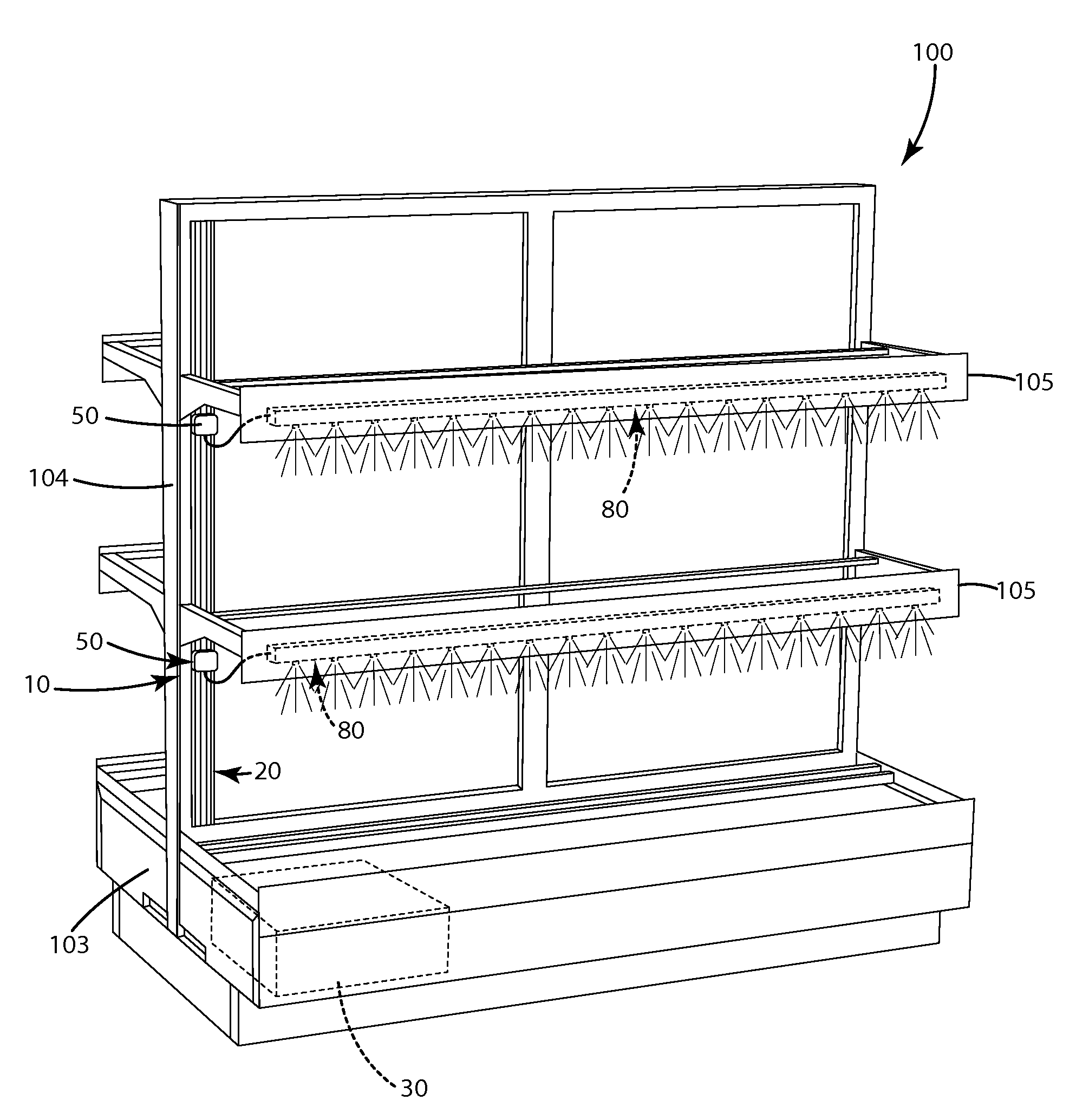
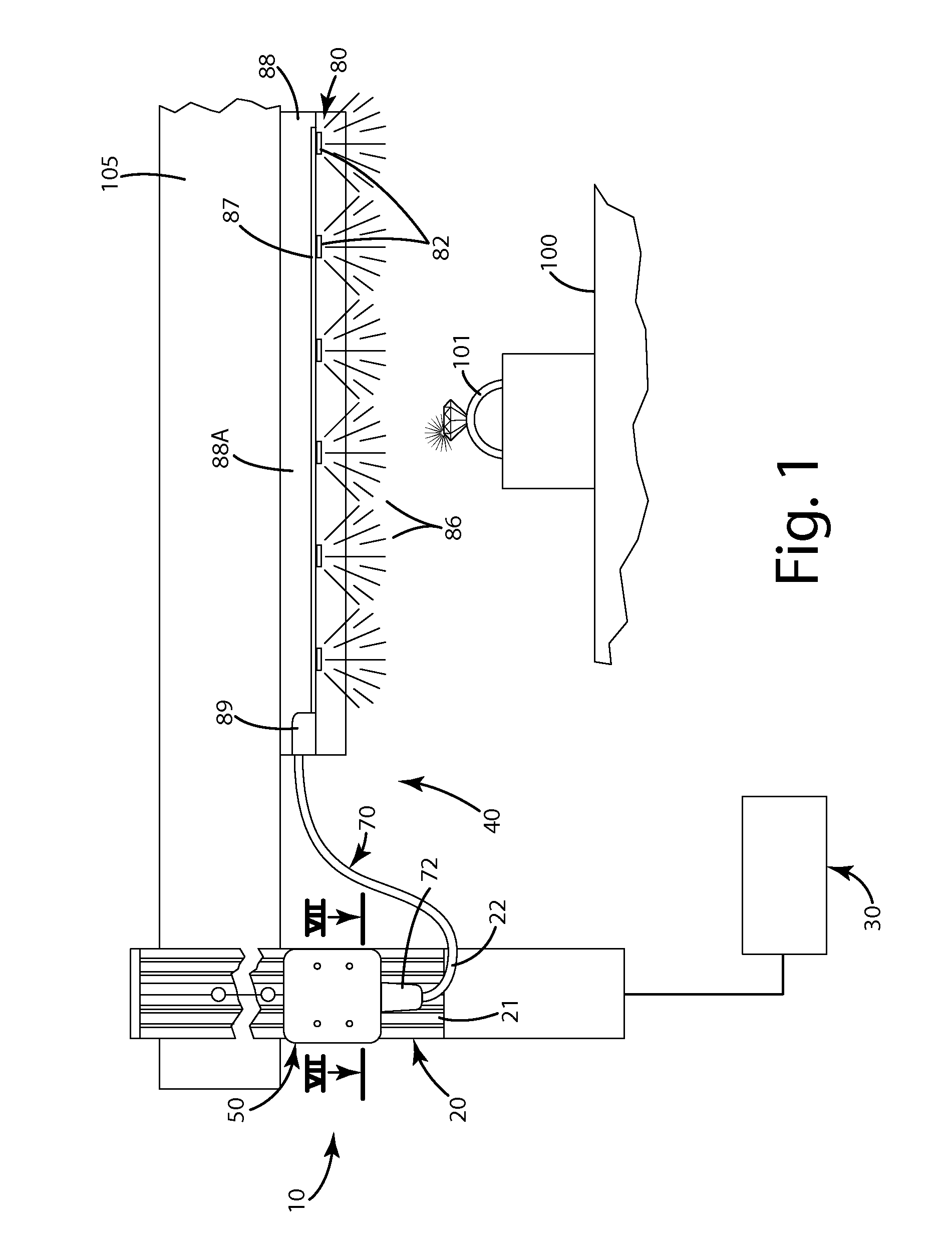
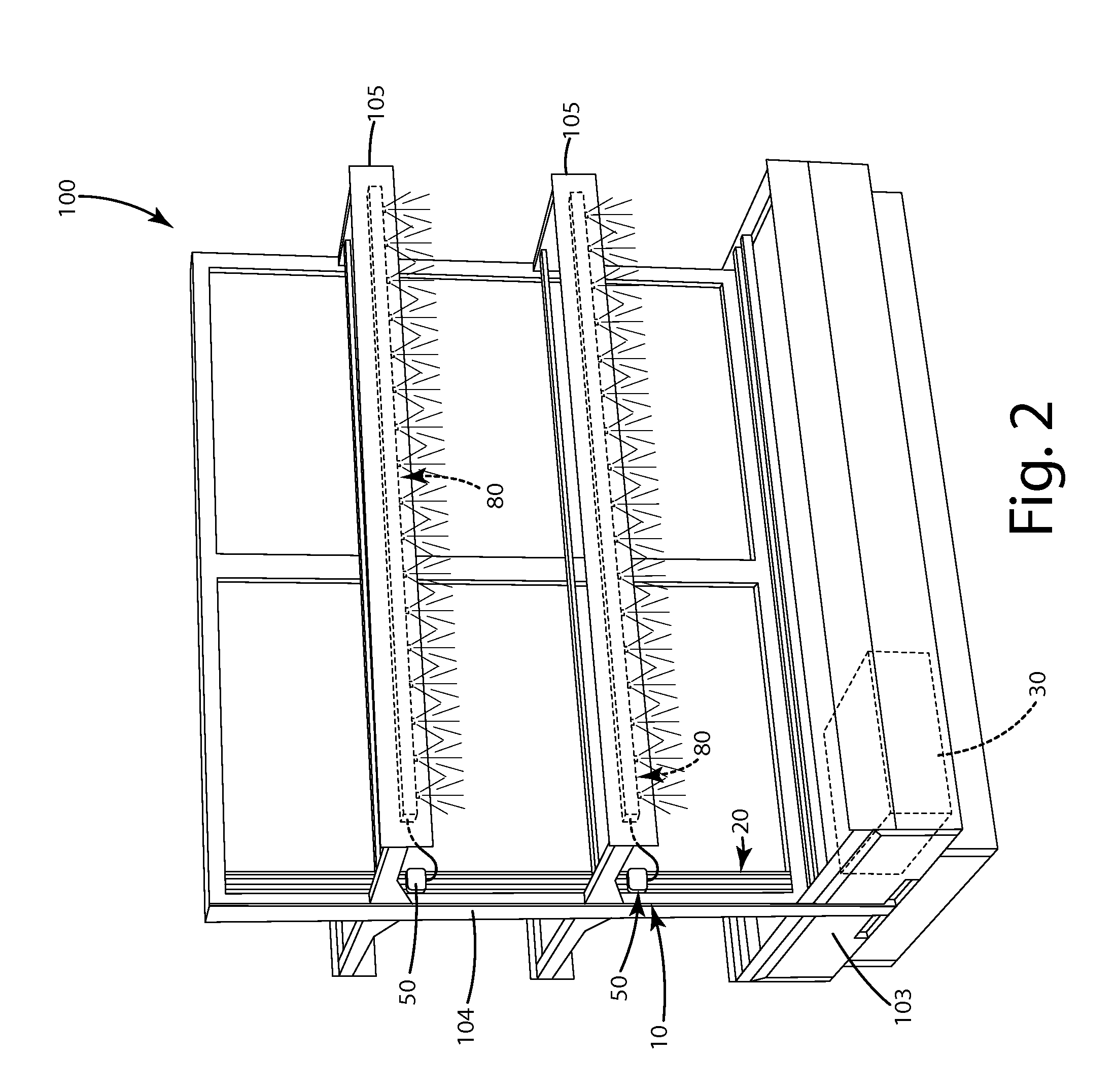
[0023]A lighting system of a current embodiment associated with a display unit is illustrated in FIGS. 1-2 and generally designated 10. The lighting system 10 can include a low voltage power frame 20 that is coupled to a power source 30. A movable light module 40 including a puck 50, an electrical coupler 70 and a lighting array 80 can be oriented with the puck 50 selectively and movably attached to the low voltage power frame 20. The puck 50 can be moved vertically along the frame to establish electric communication between it and the power frame as described in further detail below.

[0024]Generally, the puck is held to the frame only via a magnetic force that can be overcome by manual force of a user, so that the puck can be moved to another section of the frame. The coupler 70 can extend from the puck 50 to the light array 80, thereby establishing electrical communication between the puck and the light array 80. In this manner, electricity can be transferred from the power frame 2...


PUM


Abstract

A lighting system including a low voltage frame, a puck magnetically joinable with the frame, a lighting array, and an elongated electrical connector joining the puck and the lighting array. The puck can be selectively positioned along the low voltage frame in a variety of different locations. The puck can be constructed from a polymeric material molded over electrical connectors, and optionally a power feed, such as a cable jack. The electrical connectors can be magnetized so that the electrical connectors are magnetically attracted to power rails on the low voltage frame to establish electrical coupling of the connectors to the power rails, while physically securing the puck in a fixed location along the low voltage frame. The power rails can be constructed from magnetic stainless steel, optionally coated with black oxide from a hot black oxide coating process.

Description

BACKGROUND OF THE INVENTION[0001]The present invention relates to lighting systems, and more particularly to lighting systems having manually moveable and repositionable lighting modules and lighting elements.[0002]In many modern lighting systems, it is desired to have a significant degree of flexibility in a user's ability to control the direction, intensity, and characteristics of light emitted from the system. In retail or commercial settings, track lighting, individual halogen lights, or fixed LED lighting arrays often are used to illuminate merchandise and displays. This lighting can be incorporated into the structure of the building or into individual display units.[0003]While some of these lighting systems are flexible, they suffer shortcomings. For example, many are relatively large in the sense that the fixtures are conspicuous. In some applications, such as jewelry and fine goods displays, it is desirable for the lighting to be as inconspicuous as possible. In another exam...

Claims


Application Information

Patent Timeline
Patent Type & Authority Applications(United States)
IPC IPC(8): F21V23/00H01R27/02F21V21/34F21V23/06F21S4/00F21V21/005
CPCF21V23/008F21S4/008F21V21/005F21V21/34F21V23/06H01R27/02F21W2131/405H01R24/38H01R25/142H01R25/145H01R25/147F21Y2103/10F21Y2115/10A47F11/10H01R13/6205F21S4/20F21S4/28A47F7/02F21V17/105F21V23/001
Inventor WAALKES, JAMES W.VAN SLUYTERS, RYAN A.
Owner AMSTORE
Why Eureka
Try Eureka