Environment measuring device and environment measuring method

Active Publication Date: 2016-03-03
FUJITSU LTD
View PDF6 Cites 6 Cited by
  • Summary
  • Abstract
  • Description
  • Claims
  • Application Information

AI Technical Summary

Benefits of technology

[0006]According to an aspect of the embodiments, an environment measuring device has a measuring QCM sensor, a reference QCM sensor, a measurement oscillation circuit, a reference oscillation circuit, a frequency counter, s humidity sensor, a storage unit, and a control unit. The measuring QCM sensor has an oscillator and an electrode formed by a corrosive metal on the surface of the oscillator, and the reference QCM sensor has an oscillator and an electrode formed by a corrosion-resistant metal on the surface of the oscillator. The measurement oscillation circuit transmits a measurement frequency signal having a frequency in accordance with the number of oscillations of the measuring QCM sensor as well as oscillating the measuring QCM sensor. The reference oscillation circuit transmits a reference frequency signal having a frequency in accordance with the number of oscillations of the reference QCM sensor as well as oscillating

Problems solved by technology

The corrosive gas may deteriorate the performance of electronic equipment by corroding members, such as m

Method used


Image

  • Environment measuring device and environment measuring method
  • Environment measuring device and environment measuring method
  • Environment measuring device and environment measuring method

Examples


Embodiment Construction

[0031]In the following, with reference to the drawings, an environment measuring device according to the present invention is explained. However, it should be noted that the technical scope of the present invention is not limited to those embodiments, however encompasses the inventions described in the claims and equivalents thereof.

[0032]First, an environment measuring device related to the present invention is explained.

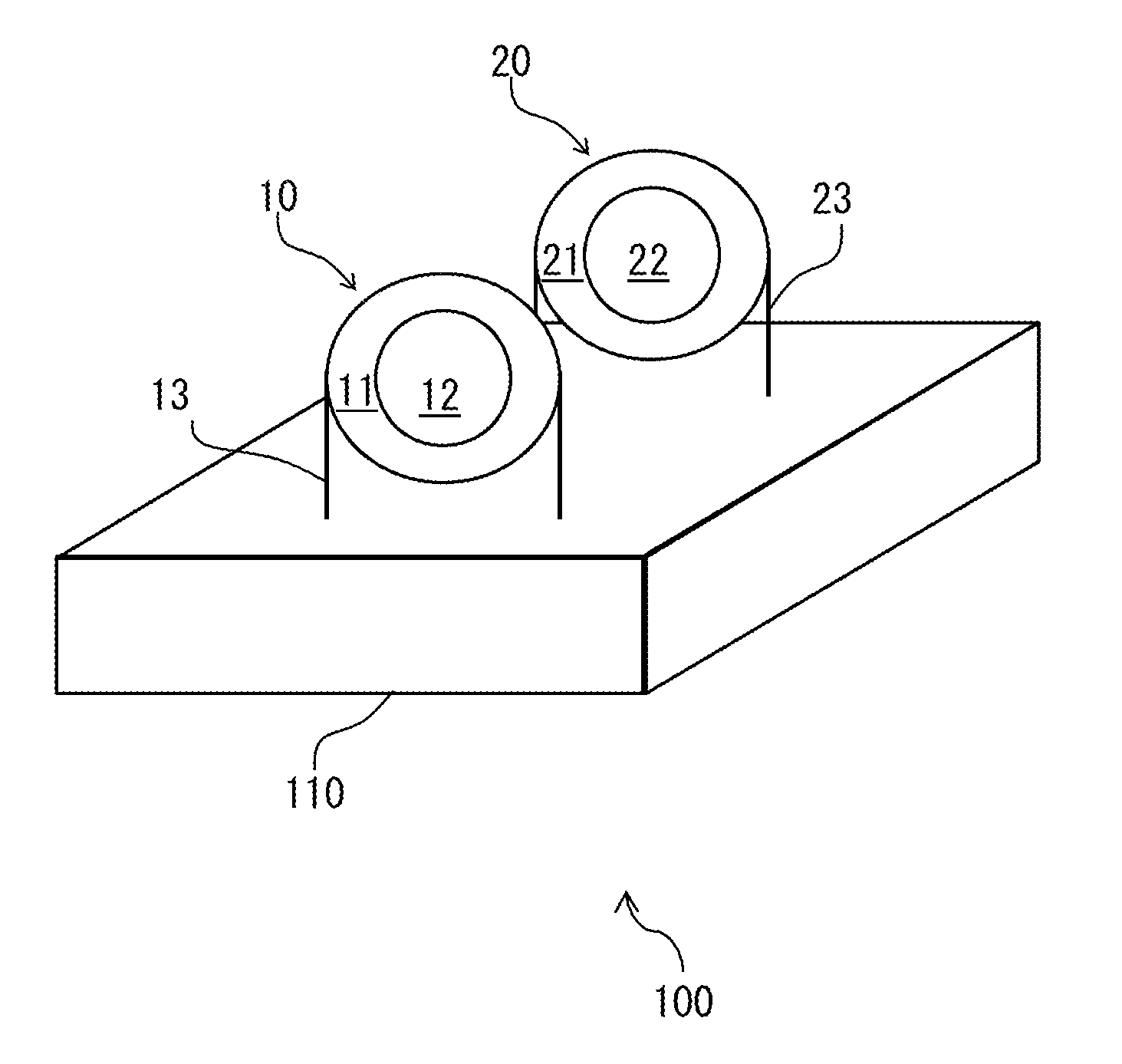
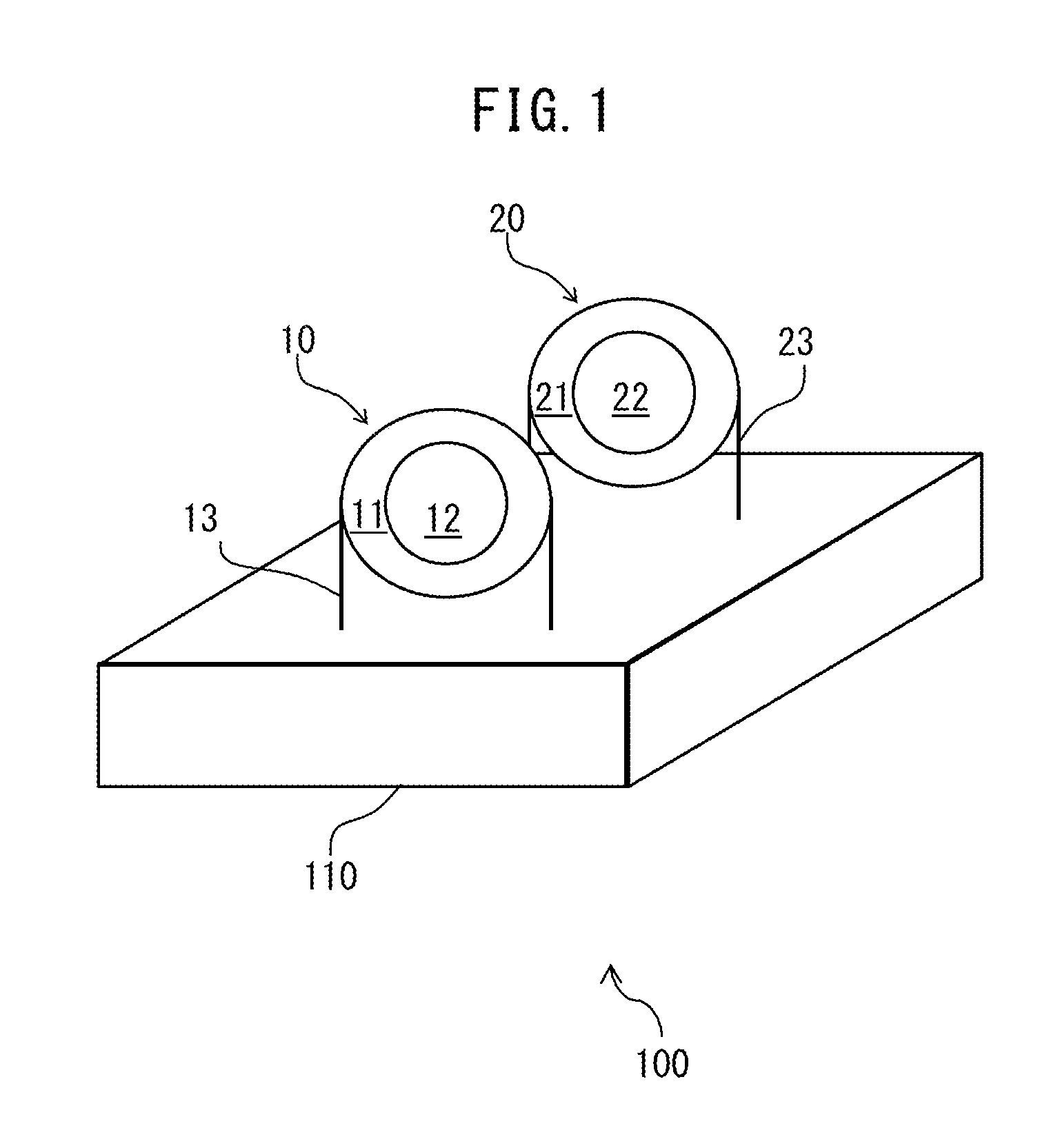
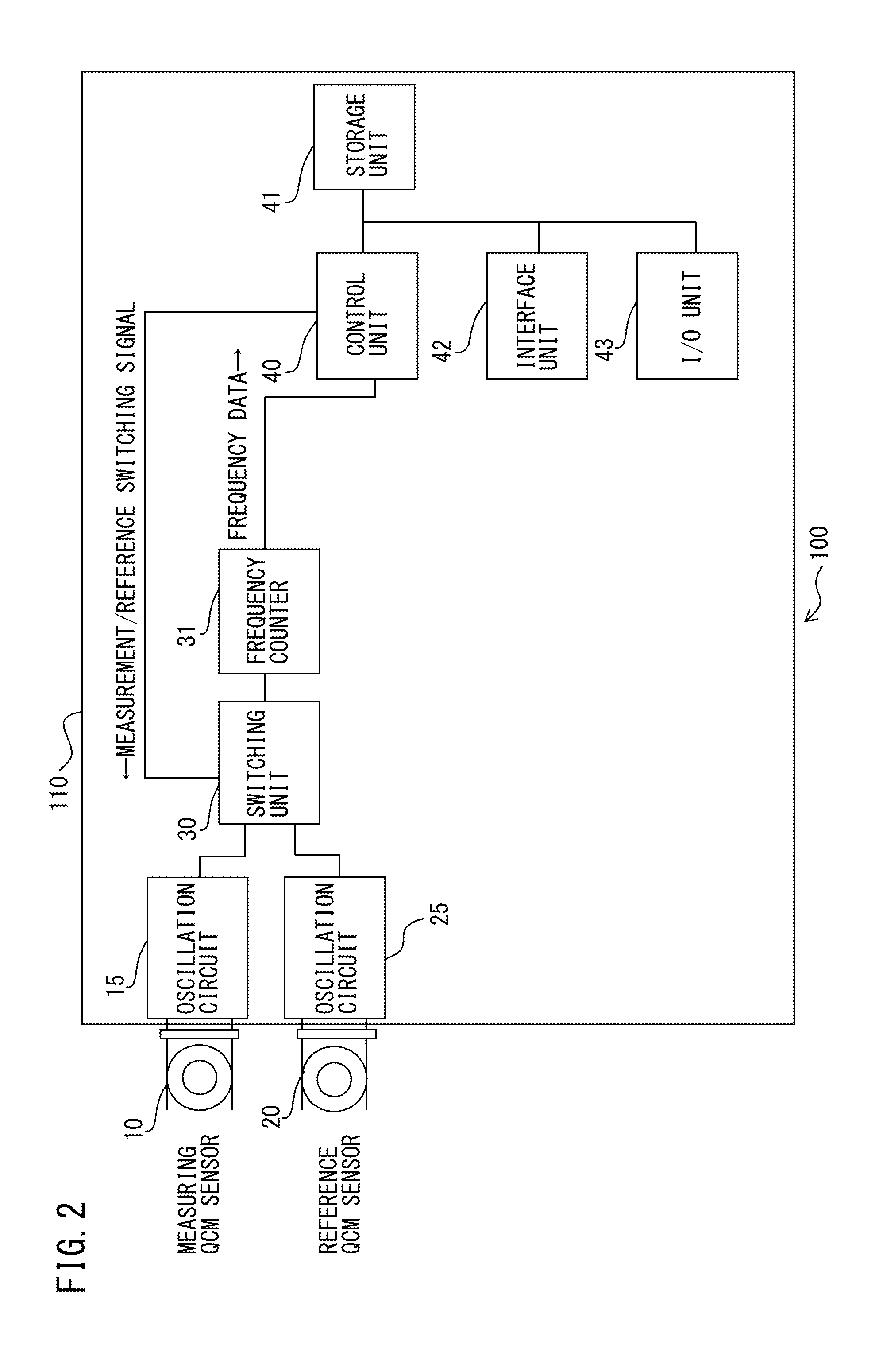
[0033]FIG. 1 is a perspective view of a related environment measuring device and FIG. 2 is a circuit block diagram of the environment measuring device illustrated in FIG. 1.

[0034]An environment measuring device 100 has a measuring QCM sensor 10, a reference QCM sensor 20, a measurement oscillation circuit 15, a reference oscillation circuit 25, a switching circuit 30, and a frequency counter 31. The environment measuring device 100 further has a control unit 40, a storage unit 41, an interface unit 42, and an I / O unit 43.

[0035]The measuring QCM sensor 10 has a quar...


PUM


Abstract

An environment measuring device 1 has a measuring QCM sensor 10, a reference QCM sensor 20, a measurement oscillation circuit 15, a reference oscillation circuit 25, a frequency counter 31, s humidity sensor 51, a control unit 40, and a storage unit 41. The measuring QCM sensor 10 has an oscillator and an electrode formed by a corrosive metal on the surface of the oscillator, and the reference QCM sensor 20 has an oscillator and an electrode formed by a corrosion-resistant metal on the surface of the oscillator. The storage unit 41 stores the measurement count signal, the reference count signal, and the humidity signal which are associated with a measurement time. The control unit 40 determines an amount of increase in mass due to the corrosion of the electrode of the measuring QCM sensor by using the measurement count signal and the reference count signal.

Description

CROSS-REFERENCE TO RELATED APPLICATION[0001]This application is a continuation application of International Patent Application No. PCT / JP2013 / 064513, filed on May 24, 2013, and designated the U.S., the entire contents of which are incorporated herein by reference.FIELD[0002]The present invention relates to an environment measuring device and an environment measuring method.BACKGROUND[0003]Electronic equipment, such as a server and an electronic computer, is installed inside buildings, such as factories and office buildings. A corrosive gas, such as hydrogen sulfide and sulfur dioxide, is often included in an environment in which electronic equipment is installed. The corrosive gas may deteriorate the performance of electronic equipment by corroding members, such as metal, forming the electronic equipment and further, may disable the operation of the electronic equipment. It is preferable to continuously monitor the corrosive gas in the environment in which the electronic equipment i...

Claims


Application Information

Patent Timeline
IPC IPC(8): G01N29/02G01N27/12
CPCG01N5/02G01N27/121G01N2291/021G01N29/022
Inventor TAKASU, RYOZO
Owner FUJITSU LTD
Why Eureka
Try Eureka