Foot drop device

a technology for dropping devices and feet, applied in the field of ankle support, can solve the problems of affecting the function of the foot, reducing mobility, and lack of muscular control to raise the foot back, and achieves the effects of increasing activity, good plantarflexion, and increasing footwear selection

Inactive Publication Date: 2016-03-10
MALINOWSKI SUZANNE
View PDF14 Cites 36 Cited by
  • Summary
  • Abstract
  • Description
  • Claims
  • Application Information

AI Technical Summary

Benefits of technology

[0075]FIG. 19 depicts movement of the foot 1900 including dorsiflexion 1905; plantarflexion 1910; inversion 1915; and eversion 1920. The stages of walking consist of repeated gait cycles. The gait cycle contains two main phases, stance phase and swing phase. The two front clip connections lift the front of the foot up providing dorsiflexion during the swing phase. On the end of the swing phase when entering the stance phase, surprisingly good plantarflexi...

Problems solved by technology

Foot drop, also known as drop foot, is a condition commonly characterized by difficulty or inability to lift the front portion of one or both feet during walking or running due to nerve damage causing weakened or paralysis of the muscles in the anterior portion of the lower leg, affecting the function of the foot.
Those with foot-drop typically otherwise have sufficient muscular control to move the foot relative to the ankle in plantarflexion (downward motion), but lack muscular control to subsequently raise the foot back up for the next step (dorsiflexion).
Without wearing any type of brace, mobility is greatly decreased, tripping/falling hazards are present and, over time, compensatory walking patterns can cause back, hip, knee, ankle, and foot issues and injuries.
Available rigid braces are characterized by limited flexibility, restricting normal and desirable foot and ankle motion resulting in an awkward gait.
Although more recent braces may allow for a slightly higher degree of flexibility using light-weight materials, the nature of the rigid brace still presents the same overall concerns.
Rigid braces for foot drop are designed to keep the foot and leg at a fixed 90 degree angle at all times, contributing to muscle atrophy from limited movement and use.
Additionally, a rigid brace does not allow the leg muscles and ankle to get the important flexibility/exercise needed and loss of muscle, ankle strength, and flexibility is a result.
Shoe selection to accommodate rigid braces is extremely limited.
Sneakers and a limited variety of available shoes with laces or a Velcro® strap (which are characteristically not designed for fashion) fit the brace and hold it in place securely.
Wearing dress shoes, heels, sandals, or any shoe without laces, Velcro® strap, or a flat heel is not an option.
A user cannot wear pants with a tapered leg as they don't fit over the brace.
The shoe is stretched, and eventually rips inside due to the brace strut and continuous movement of the footplate.
Wearers find that rigid braces tend to break from various repetiti...

Method used


Image

  • Foot drop device
  • Foot drop device
  • Foot drop device

Examples


first embodiment

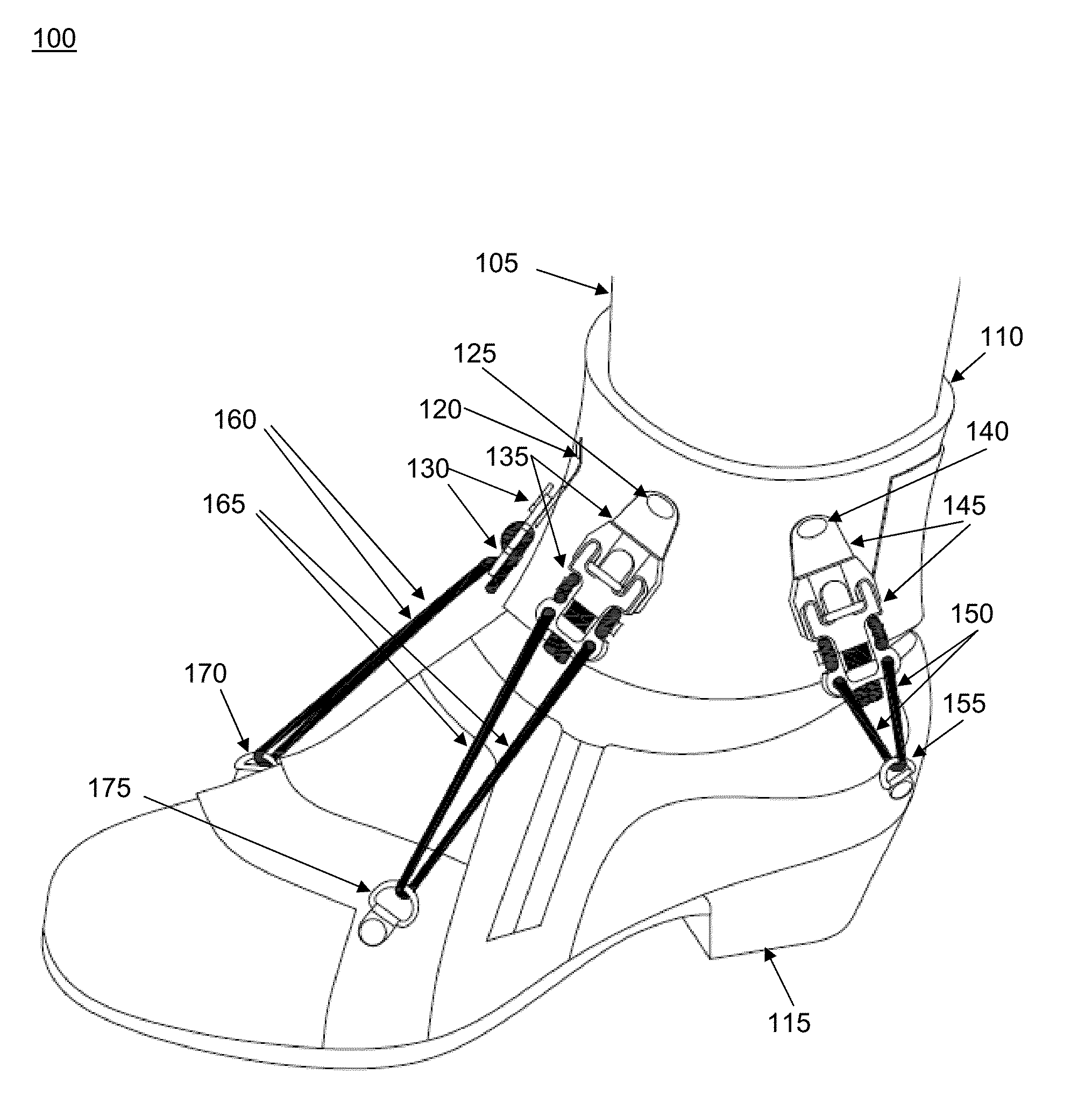
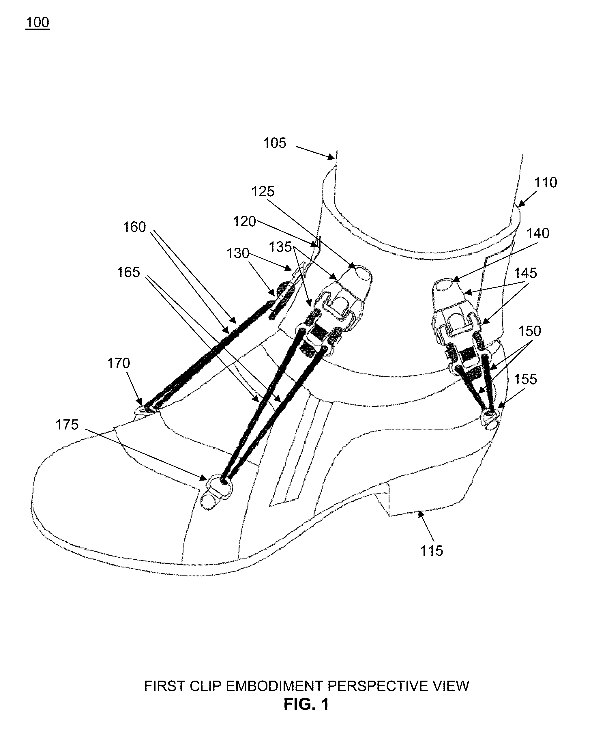
[0057]FIG. 1 shows a perspective view 100 of a first embodiment depicting leg 105; comprising ankle component 110; shoe 115; first front ankle attachment 120; second front ankle attachment 125; first front ankle clip component 130; second front ankle clip component 135; side attachment 140; side clip component 145; side elastic components 150; shoe side attachment located on the quarter area of the footwear 155; first front elastic components 160; second front elastic components 165; first front shoe attachments 170; and second front shoe attachments located on the vamp area of the footwear 175.

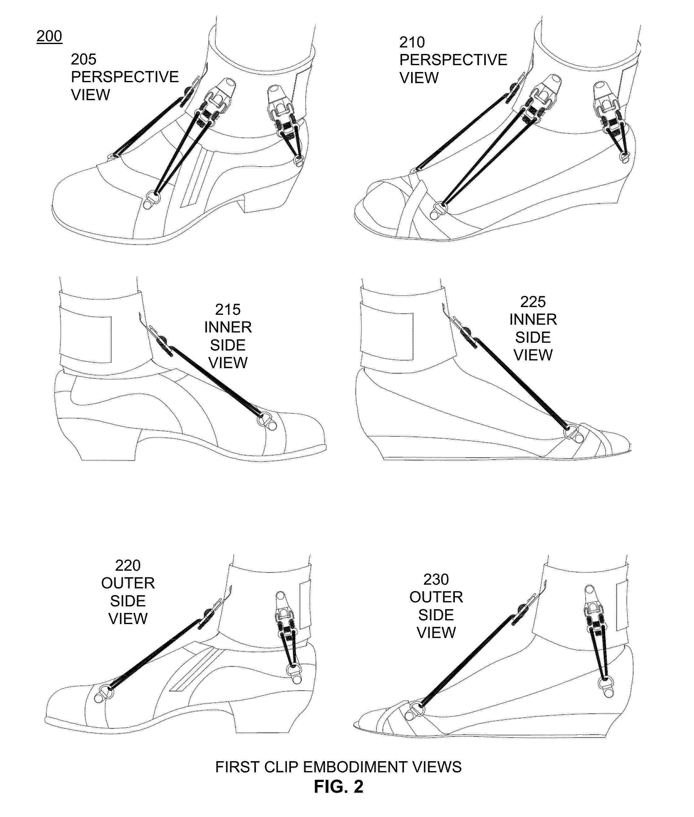
[0058]FIG. 2 illustrates views 200 of a first embodiment. Views are first perspective view 205; second perspective view 210; inner side view 215 of first perspective view 205; outer side view 220 of first perspective view 205; inner side view 225 of second perspective view 210; and outer side view 230 of second perspective view 210.

[0059]FIG. 3 illustrates additional views 300 of a first embo...

second embodiment

[0065]FIG. 9 shows a perspective view 900 of a second embodiment utilizing an o-ring and hook attachment depicting leg 905; comprising ankle component 910; shoe 915; first front ankle attachment 920; second front ankle attachment 925; first front ankle clip component 930; second front ankle clip component 935; side attachment 940; side clip component 945; side elastic components 950; first shoe side attachment showing an embodiment where holes are punched directly into the shoe disregarding the need for a D-ring 955; first front elastic component 960; second front elastic component 965; first front shoe attachments showing an embodiment utilizing the existing eyeholes in the sneakers 970; and second front shoe attachments utilizing the existing eyeholes in the sneaker 975.

[0066]FIG. 10 illustrates views 1000 of a second embodiment. Views are outer side view 1005; and inner side view 1010.

[0067]FIG. 11 illustrates views 1100 of a second embodiment. Views are perspective view 1105; ou...

third embodiment

[0071]FIG. 15 is a perspective view 1500 of a third embodiment depicting D-ring detail.

[0072]FIG. 16 is a detail scale view 1600 of cord connector clip components for embodiments. Four views include first embodiment side view A, first embodiment front view B, first embodiment back view C (with buckle D attached), and cord connector buckle button attachment D. Each clip includes two apertures 1605. Rear clips 1610 (for extra elastic length for adjusting) are on the back side of view B. They are shown in this view for placement information. Rear clips 1610 hold excess elastic. Push button 1615 is shown in view B. Back view C depicts button attachment D affixed 1620. Opening 1625 for attachment to brace and opening 1630 for button are shown in view D. Interior and exterior edges are rounded. For embodiments, the button is sized for a thumb to press. In embodiments, clip notches 1635 are large enough to hold two ⅛ inch diameter elastics securely.

[0073]FIG. 17 is a detail view 1700 of an...


PUM


Abstract

This invention describes a multi-point soft flexible ankle foot brace support orthosis apparatus and method for compensating for weakness of the ankle and ankle/foot dorsiflexion resulting in steppage gait of foot drop comprising an ankle cuff that is securely connected to footwear by way of clips and elastic cords, allowing for natural walking motion. The connection of the ankle cuff to the shoe is secure, yet adjustable to accommodate each user's individual need and is easily fastened and unfastened for daily use.

Description

RELATED APPLICATION[0001]This application claims the benefit of U.S. Provisional Application No. 62 / 046,272 filed Sep. 5, 2014, incorporated herein by reference in its entirety for all purposes.FIELD OF THE INVENTION[0002]The invention relates to the field of foot and ankle support. Particularly, an ankle-foot orthosis apparatus and a method for providing long-term walking assistance compensating for weakness of ankle and toe dorsiflexion resulting in steppage gait of foot drop, or difficulty in lifting the front of the foot off the ground.BACKGROUND OF THE INVENTION[0003]Foot drop, also known as drop foot, is a condition commonly characterized by difficulty or inability to lift the front portion of one or both feet during walking or running due to nerve damage causing weakened or paralysis of the muscles in the anterior portion of the lower leg, affecting the function of the foot. Foot drop is compensated for by lifting the foot higher than normally necessary to avoid tripping over...

Claims


Application Information

Patent Timeline
IPC IPC(8): A61F5/01
CPCA61F5/0113A61F2005/0167A61F2005/0179
Inventor MALINOWSKI, SUZANNEZRATE, CHADHAMILTON, KATHERINE ANN
Owner MALINOWSKI SUZANNE
Why Eureka
Try Eureka