Apparatus, system, and method for vending, charging, and two-way distribution of electrical energy storage devices

Active Publication Date: 2016-03-10
GOGORO
View PDF5 Cites 38 Cited by
  • Summary
  • Abstract
  • Description
  • Claims
  • Application Information

AI Technical Summary

Benefits of technology

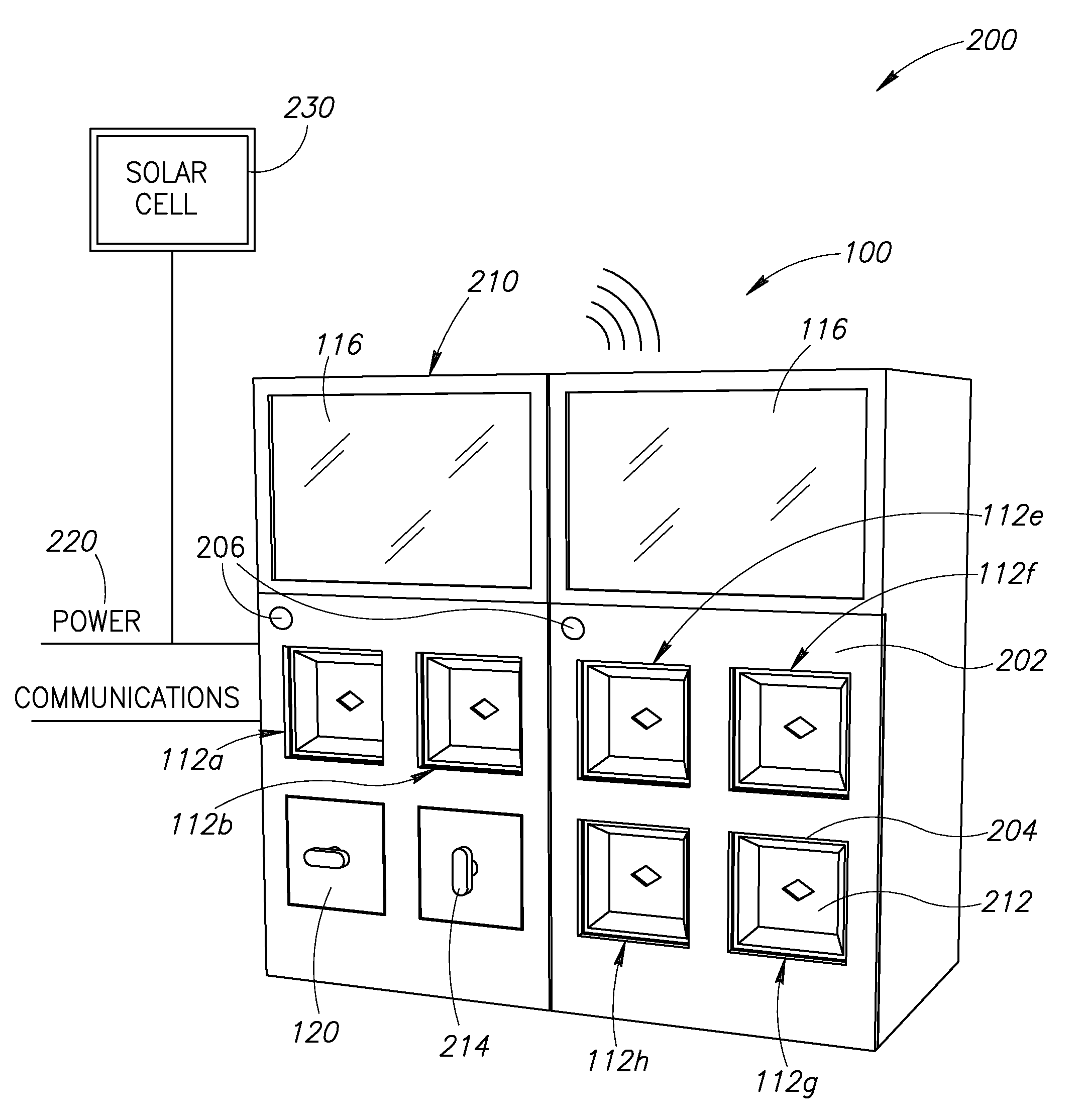
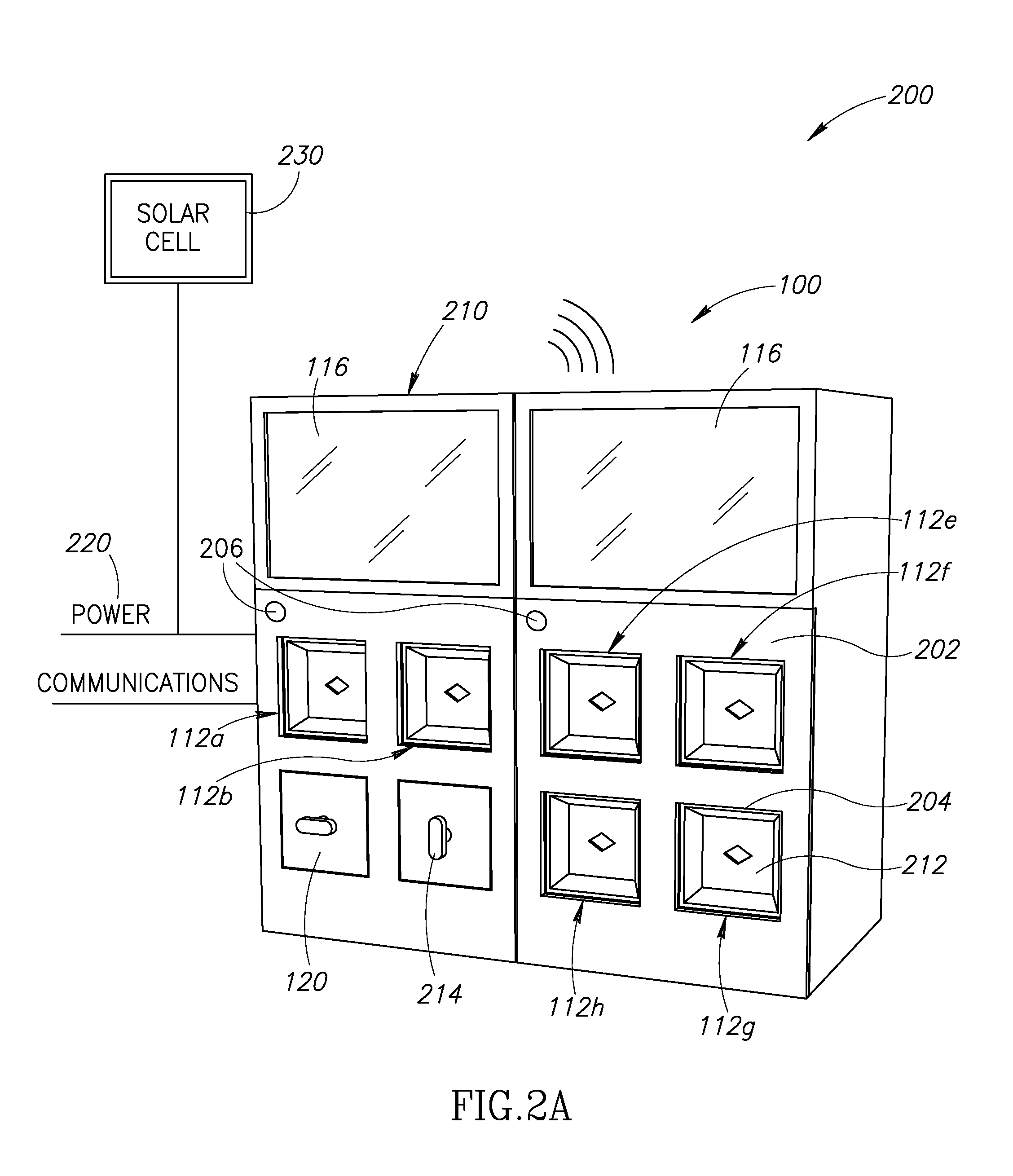
[0011]The modular design of the charging modules eliminates the need to field-service a malfunctioning charging module, a significant advantage in areas where inclement weather is common and access to electronic diagnostic tools is limited. Each charging module is electrically isolated from every other charging module in the two-way distribution, charging, and vending system, thus a failure of a single charging module does not adversely affect the operation of other charging modules or the two-way distribution, charging, and vending system as a whole. The two-way distribution, charging, and vending systems may include a modular construction that enables the modules to be physically, electrically, and communicably linked to form a two-way distribution, charging, and vending system having any number of charging modules. Such modular construction is advantageous to accommodate an increasing number of users in a minimally disruptive manner (i.e., two-way distribution, charging, and vending systems are not replaced, but are instead expanded to accommodate subscriber growth).
[0012]The charging module incorporates a displaceable housing door. Springs or other biasing members bias the displaceable housing door toward the entrance of the charging module. The displaceable housing door incorporates or seats against a weatherproof seal that limits or prevents the ingress of rainwater, dust, and dirt into the charging module. The act of inserting the portable electrical energy storage device displaces the housing door along a longitudinal axis of the charging module. An aperture on the housing door permits a locking hub in the base of the charging module to pass through the displaceable door and engage a complimentary cavity on the portable electrical energy storage device, securing the portable electrical energy storage device in the charging module. The aperture also permits the passage of a number of electrical contacts to engage a complimentary number of electrical contacts on the portable electrical energy storage device, thereby permitting the flow of current from the two-way distribution, charging, and vending system to the portable electrical energy storage device.
[0023]The method may further include responsive to unsuccessfully authenticating the first portion of the data or responsive to unsuccessfully validating the second portion of the data: displacing an actuator operably coupled to the locking hub in the first of the number of charging modules from a first position to a second position to sufficient displace the locking hub in the first of the number of charging modules from the first (locked) position to a second (unlocked) position thereby permitting the removal of the first portable electrical energy storage device from the first of the number of charging modules; and maintaining an actuator operably coupled to the locking hub in the second of the number of charging modules in a first position sufficient to maintain the locking hub in the second of the number of charging modules in the first (locked) position thereby preventing the removal of the second portable electrical energy storage device from the second of the number of charging modules.
[0030]The method may further include positioning an actuator operably coupled to a locking hub in the first charging module in a first position sufficient to position the locking hub in the first charging module in a first (locked) position thereby preventing the removal of the first portable electric energy storage device from the first of the number of charging modules.

Problems solved by technology

One of the primary impediments to widespread acceptance of electric or battery powered vehicles is the ready availability of charged portable electrical energy storage devices to avoid leaving drivers stranded for extended periods while recharging.
This issue is particularly acute in regions and areas that are susceptible to interruptions in electrical distribution and / or delivery.

Method used


Image

  • Apparatus, system, and method for vending, charging, and two-way distribution of electrical energy storage devices
  • Apparatus, system, and method for vending, charging, and two-way distribution of electrical energy storage devices
  • Apparatus, system, and method for vending, charging, and two-way distribution of electrical energy storage devices

Examples


Embodiment Construction

[0051]In the following description, certain specific details are set forth in order to provide a thorough understanding of various disclosed embodiments. However, one skilled in the relevant art will recognize that embodiments may be practiced without one or more of these specific details, or with other methods, components, materials, etc. In other instances, well-known structures associated with controllers and / or microprocessors and associated programming, logic , and / or instruction sets; AC / DC power converters; buck and boost transformers; thermal control systems; portable electric energy storage devices (e.g., secondary batteries); networks and network communication protocols; wireless communications protocols; have not been shown or described in detail to avoid unnecessarily obscuring descriptions of the embodiments.

[0052]As used herein, “operational aspects” or a reference to one or more “operational aspects” of a vehicle includes the performance or function of any combination...


PUM


Abstract

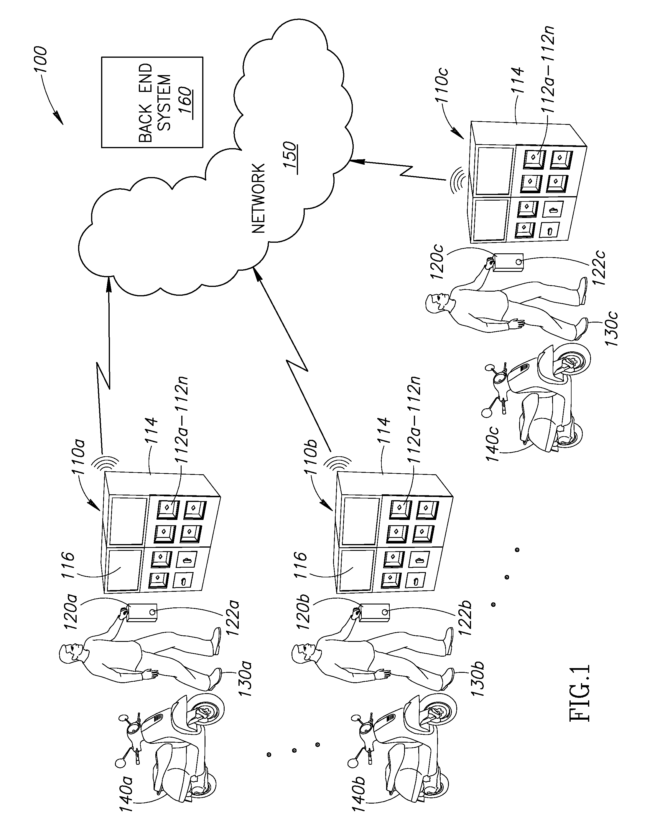
A two-way distribution, charging, and vending system permits a subscriber to exchange one or more partially or completely discharged portable electric energy storage devices for a comparable number of charged portable electric energy storage devices. The two-way distribution, charging, and vending system includes a number of charging modules, each with a dedicated power converter, communicably coupled to at least one two-way distribution system controller and to a power distribution grid. Upon receipt of a discharged portable electric energy storage device, the at least one two-way distribution system controller validates a manufacturer identifier and a subscriber identifier stored in a nontransitory storage media carried by the discharged portable electric energy storage device. Responsive to a successful authentication and validation, the at least one two-way distribution system controller dispenses a charged portable electric energy storage device to the subscriber.

Description

BACKGROUND[0001]1. Technical Field[0002]The present disclosure generally relates to the vending, charging, and two-way distribution of electrical energy storage devices.[0003]2. Description of the Related Art[0004]Electric powered vehicles are gaining in popularity worldwide. One of the primary impediments to widespread acceptance of electric or battery powered vehicles is the ready availability of charged portable electrical energy storage devices to avoid leaving drivers stranded for extended periods while recharging. This issue is particularly acute in regions and areas that are susceptible to interruptions in electrical distribution and / or delivery. Providing a readily available source of charged portable electric storage devices in a number of convenient locations may ameliorate the worries of many drivers and may foster the widespread acceptance of electric vehicles, particularly in highly congested urban areas. Adoption of electric vehicle technology on a widespread basis may...

Claims


Application Information

Patent Timeline
Patent Type & Authority Applications(United States)
IPC IPC(8): B60L11/18
CPCB60L11/1838B60L11/1822B60L53/51B60L53/665B60L53/80B60L53/18B60L53/65Y02T90/16Y02T90/14Y04S30/14G07F7/06G07F15/006B60L2240/545B60L2240/70B60L2250/20B60L2270/34B60L58/16B60L58/26B60L58/27B60L53/305B60L53/30B60L53/16B60K2001/0494H02J7/0044H02J7/00036H02J7/00045B60Y2200/126B60K1/00Y02T10/70Y02T10/7072Y02T10/72Y02T90/12Y02T90/167
Inventor CHEN, JUNG-HSIUCHEN, SHEN-CHIWU, YU-LINHUANG, CHIEN-MINGCHAN, TSUNGTINGYANG, FENG KAI
Owner GOGORO
Why Eureka
Try Eureka