Voltage source converter based direct current deicer and controlling method thereof

Active Publication Date: 2016-03-10
ELECTRIC POWER RESEARCH INSTITUTE, CHINA SOUTHERN POWER GRID CO LTD
View PDF3 Cites 12 Cited by
  • Summary
  • Abstract
  • Description
  • Claims
  • Application Information

AI Technical Summary

Benefits of technology

[0022]The voltage source converter based DC deicer of the present invention takes advantage of the feature of the full H-bridge submodule that can output three types of voltage, including positive voltage, zero voltage and negative voltage, so that both the voltage and current at the DC side of the DC converter are continuously adjustable between zero and a rated value. Hence the voltage source converter based DC deicer of the present invention satisfies the need of deicing power transmission lines of different length and resistivity, satisfies the need of the deicing of power transmission lines of 10 kV, 110 kV, 2

Problems solved by technology

Compared to other natural disasters, ice disaster often causes more severe damages to the power grid, such as ice flashover, wire breakage, electric tower collapse, and even a failure in power grid.
However, both of said deicers adopt thyristors, which consumes much reactive power and generates characteristic harmonic component, thu

Method used


Image

  • Voltage source converter based direct current deicer and controlling method thereof
  • Voltage source converter based direct current deicer and controlling method thereof
  • Voltage source converter based direct current deicer and controlling method thereof

Examples


embodiment 1

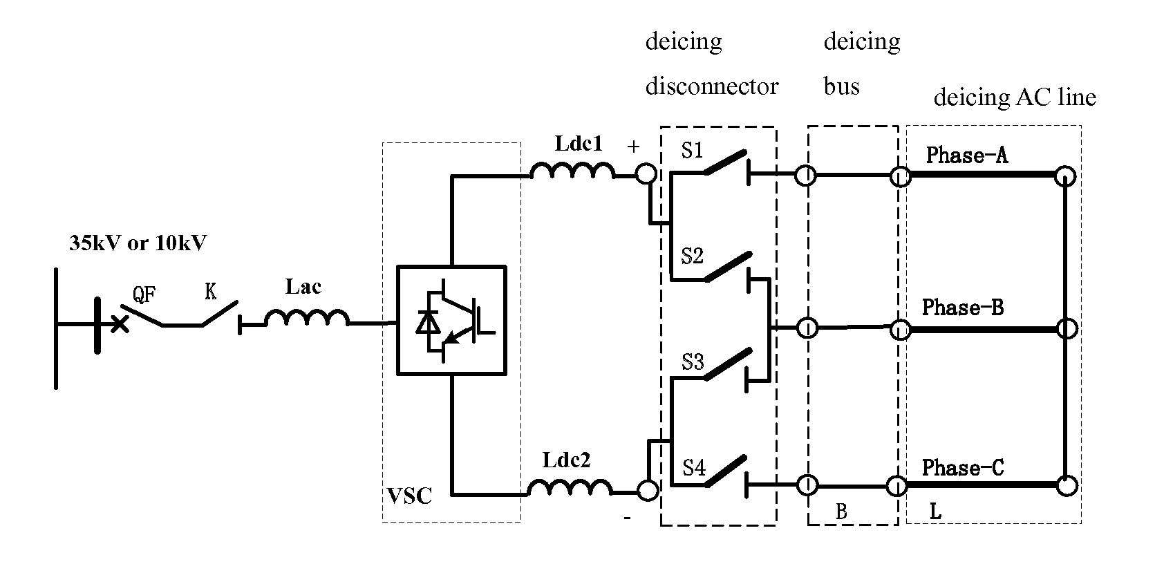
[0029]Referring to FIG. 1, this embodiment provides a voltage source converter based direct current (DC) deicer, comprising: a connecting reactor Lac; a modular multilevel voltage source converter VSC based on a full H-bridge submodule and having an alternative current (AC) side and a DC side; first and second smoothing reactors Ldc1, Ldc2; first, second, third and fourth deicing disconnectors S1, S2, S3, S4; a deicing bus B having a phase-A, a phase-B and a phase-C; and a deicing AC line L having a phase-A, a phase-B and a phase-C. One end of the connecting reactor Lac is connected to an AC side bus through an isolation disconnector K and a breaker QF connected in series, and the other end of the connecting reactor Lac is connected to the AC side of the converter VSC. The DC side of the converter VSC is connected to one end of each of the first and second smoothing reactors Ldc1, Ldc2. The other end of the first smoothing reactor Ldc1, one end of the first deicing disconnector S1 a...

embodiment 2

[0040]In this embodiment, the full H-bridge submodule of the converter VSC is a full H-bridge submodule with a plurality of fully-controlled power electronic device sets.

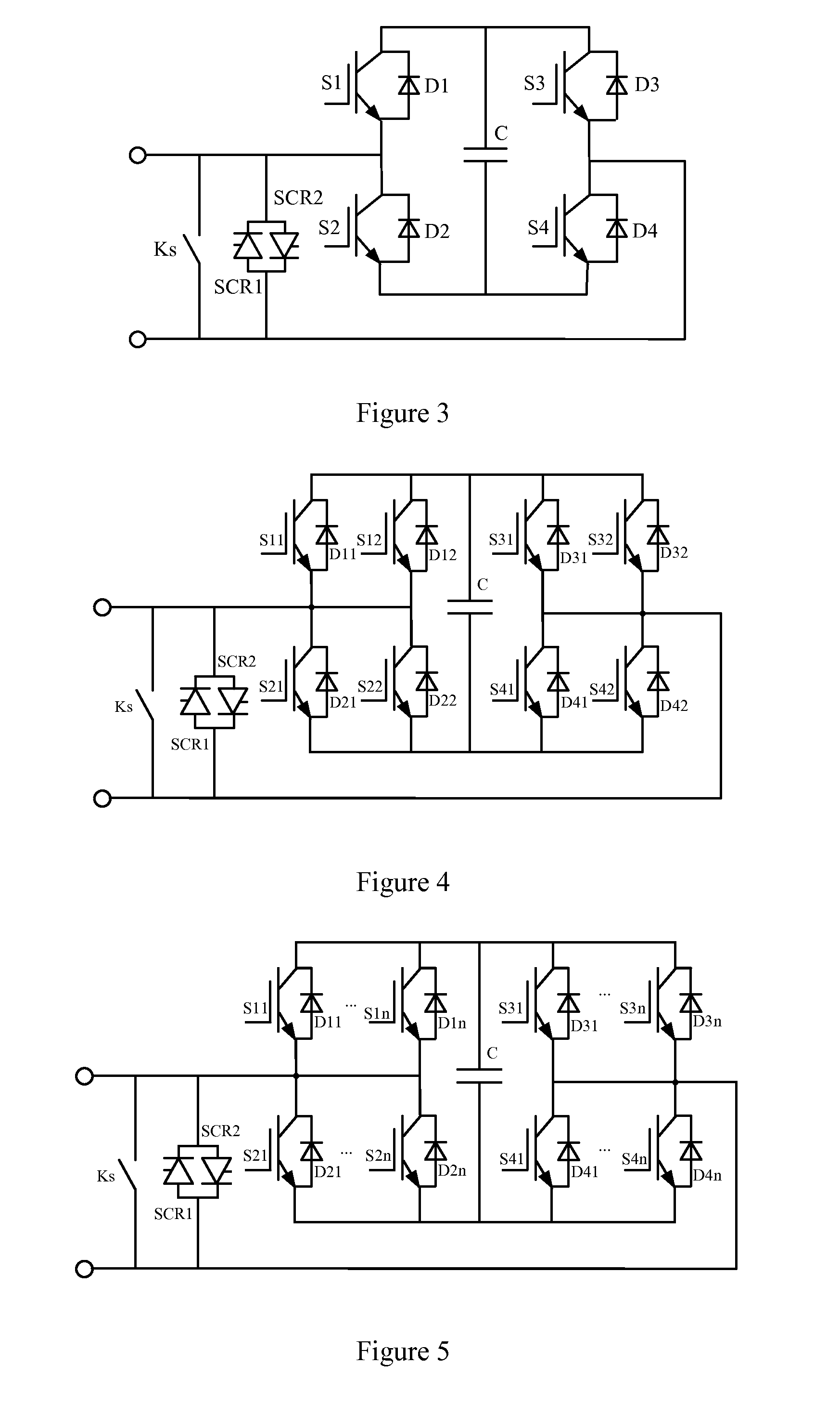
[0041]Referring to FIG. 4, the full H-bridge submodule with a plurality of fully-controlled power electronic device sets comprises: first, second, third and fourth fully-controlled power electronic device sets each having two fully-controlled power electronic device pairs each having a fully-controlled power electronic device and a diode in inverse-parallel connection (see FIG. 4, a fully-controlled power electronic device S11 and a diode D11 being in inverse-parallel connection, a fully-controlled power electronic device S12 and a diode D12 being in inverse-parallel connection, a fully-controlled power electronic device S21 and a diode D21 being in inverse-parallel connection, a fully-controlled power electronic device S22 and a diode D22 being in inverse-parallel connection, a fully-controlled power electronic dev...

embodiment 3

[0042]In this embodiment, the full H-bridge submodule of the converter VSC is a full H-bridge submodule with a plurality of fully-controlled power electronic device sets.

[0043]The full H-bridge submodule with a plurality of fully-controlled power electronic device sets comprises: first, second, third and fourth fully-controlled power electronic device sets each having three fully-controlled power electronic device pairs each having a fully-controlled power electronic device and a diode in inverse-parallel connection, a positive end of the fully-controlled power electronic device and a negative end of the diode being connected together to form a positive end of each of the fully-controlled power electronic device pairs, a negative end of the fully-controlled power electronic device and a positive end of the diode being connected together to form a negative end of each of the fully-controlled power electronic device pairs, positive ends of the three fully-controlled power electronic d...


PUM


Abstract

A voltage source converter based DC deicer and its control method are provided. The voltage source converter based DC deicer includes a connecting reactor, a modular multilevel voltage source converter based on a full H-bridge submodule, smoothing reactors, deicing disconnectors, a deicing bus, and a deicing AC line. The AC side of the modular multilevel voltage source converter is connected to an AC side bus through the connecting reactor, an isolation disconnector and a breaker. The DC side of the modular multilevel voltage source converter is connected to the deicing AC line through the smoothing reactors, the deicing disconnectors, and the deicing bus.

Description

CROSS REFERENCE TO RELATED PATENT APPLICATION[0001]This is a Continuation-In-Part Application of PCT Application No. PCT / CN2014 / 087160 filed on Sep. 23, 2014, which claims the benefit of Chinese Patent Application No. 201410083411.1 filed on Mar. 7, 2014, the entire content of which is hereby incorporated by reference.FIELD OF THE INVENTION[0002]The present invention relates to a voltage source converter based direct current (DC) deicer and controlling method thereof, which is an innovative technology applicable to the deicing of power transmission lines of a power grid. In particular, the voltage source converter (VSC) of the present invention is a modular multilevel voltage source converter based on a full H-bridge submodule.BACKGROUND OF THE INVENTION[0003]Ice disaster is one of the most serious threats to the electric power systems among all natural disasters. Compared to other natural disasters, ice disaster often causes more severe damages to the power grid, such as ice flasho...

Claims


Application Information

Patent Timeline
IPC IPC(8): H02G7/16H02M7/5387H05B3/00H05B3/06
CPCH02G7/16H05B3/0014H02M7/5387H05B3/06H05B3/0028H02M1/32H02M1/088H05B1/0227H05B2214/02H02M1/325H02M7/4835H05B3/0019
Inventor FU, CHUANGRAO, HONGWANG, JUANJUANXU, SHUKAI
Owner ELECTRIC POWER RESEARCH INSTITUTE, CHINA SOUTHERN POWER GRID CO LTD
Why Eureka
Try Eureka