
Conductive pin structure and electrical connector having the conductive pin structure

a technology of conductive pins and structures, applied in the direction of coupling devices, two-part coupling devices, electrical apparatus, etc., can solve the problems of reducing signal loss, preventing adjustment of impedance, and reducing signal loss, so as to reduce signal loss, simplify the structure of dies, and prolong the service life of dies

Inactive Publication Date: 2016-03-17
ALL BEST PRECISION TECH
View PDF0 Cites 1 Cited by
  • Summary
  • Abstract
  • Description
  • Claims
  • Application Information

AI Technical Summary

Benefits of technology

The present invention provides a conductive pin structure and an electrical connector with the conductive pin structures that can adjust impedance, reduce signal loss, simplify die structures, extend the service life of dies, speed up processing work, and streamline processing work. This means that the conductive pin structure and the electrical connector can improve the performance and efficiency of electronic devices.

Problems solved by technology

However, the technique of enclosing the conductive pins in part has a disadvantage, that is, a plastic structure connected to conductive pins increases signal loss and prevent adjustment of impedance.
The technique of enclosing some conductive pins and then exposing some other conductive pins has a disadvantage, that is, conductive pins are partially covered with a plastic structure, thus rendering signal loss reduction impossible.
Also, to expose part of the enclosed conductive pins, it is necessary that, after the plastic structure has enclosed part of the conductive pins, part of the plastic structure must be removed with a die, thereby complicating die structures, shortening the service life of dies, slowing down processing work, and complicating processing work.

Method used


Image

  • Conductive pin structure and electrical connector having the conductive pin structure
  • Conductive pin structure and electrical connector having the conductive pin structure
  • Conductive pin structure and electrical connector having the conductive pin structure

Examples


Embodiment Construction

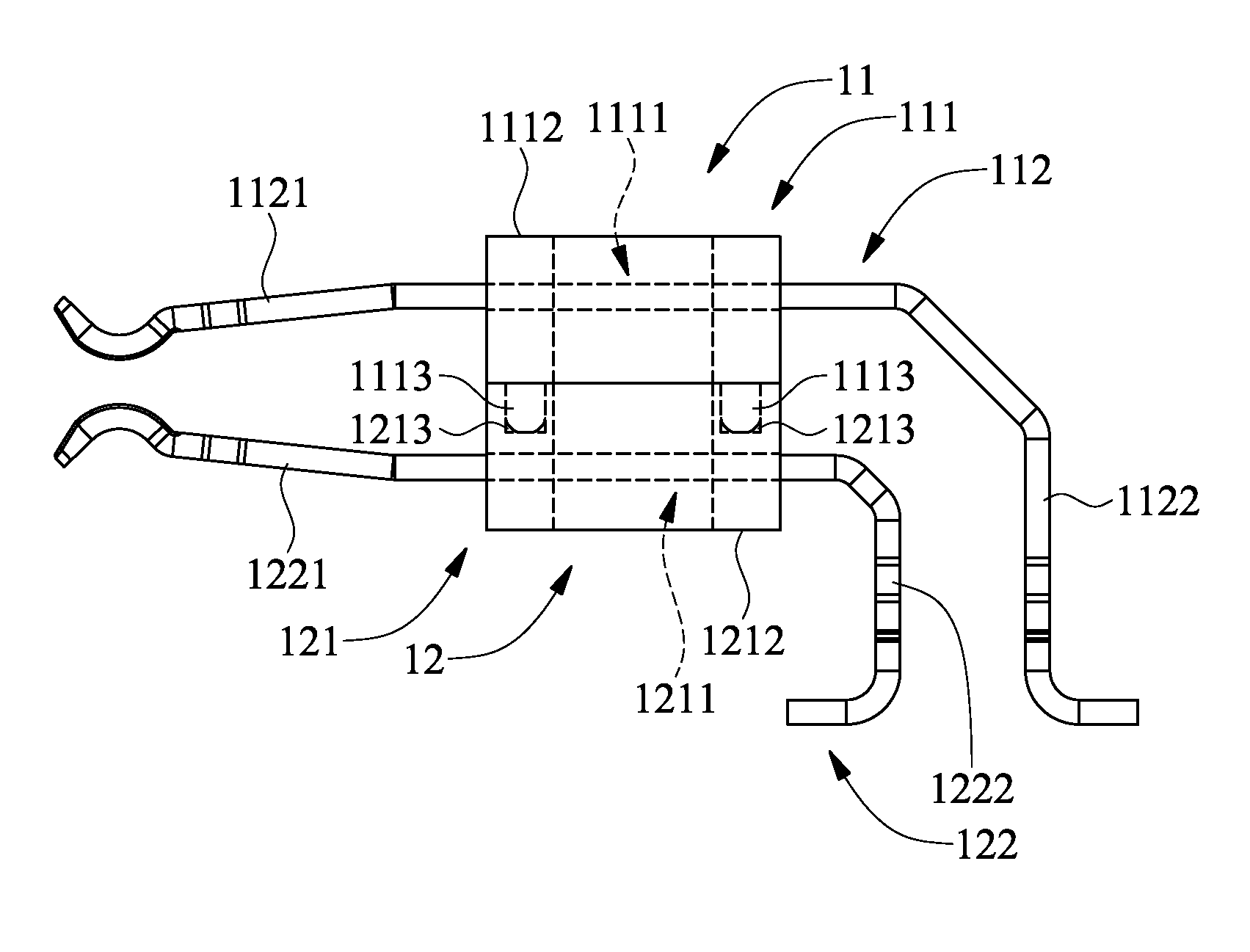
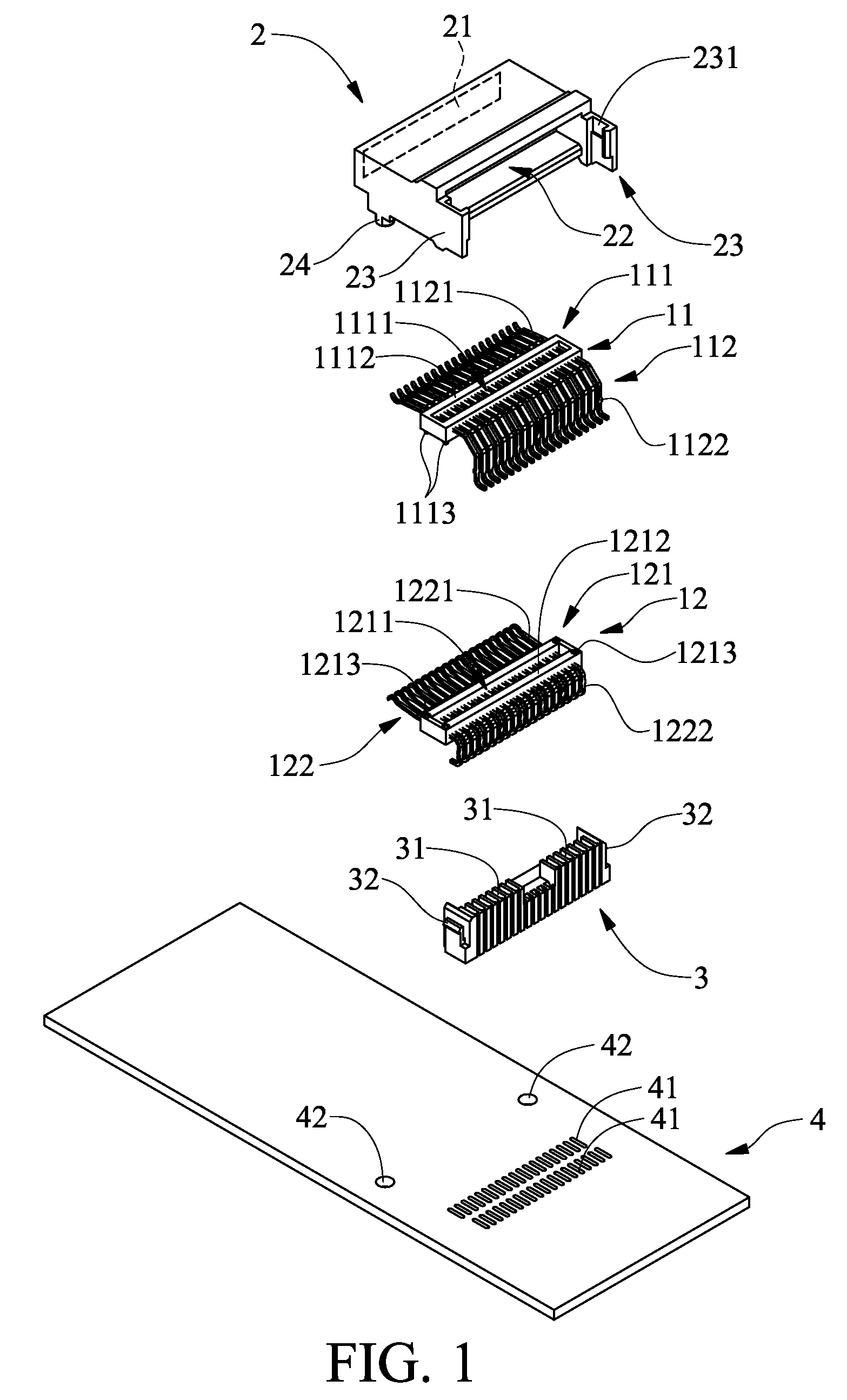
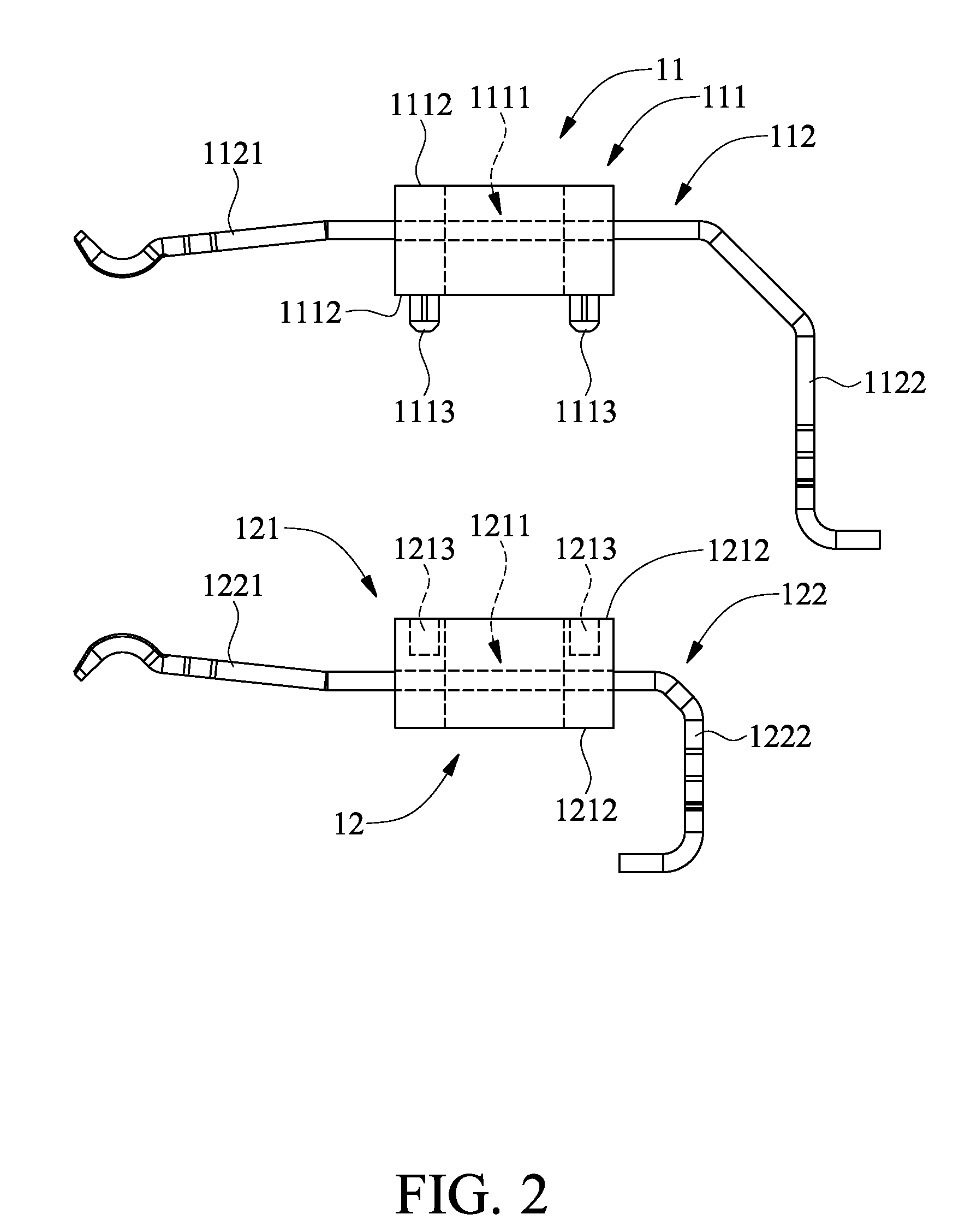
[0026]Referring to FIG. 1 and FIG. 2, the present invention provides a conductive pin structure 11 which comprises a frame 111 and a plurality of conductive pins 112. The frame 111 is made of a plastic and has a hollow-core region 1111. The conductive pins 112 are arranged transversely and spaced apart. The conductive pins 112 are longitudinally, insertedly, and fixedly disposed on two sides of the frame 111 and pass through the hollow-core region 1111 of the frame 111. The conductive pins 112 are coupled to the frame 111 by insert molding. The conductive pins 112 are disposed in an electrical connector because of the frame 111. The conductive pins 112 each have a resilient electrical contact segment 1121 and an electrical connection segment 1122 connected to the resilient electrical contact segment 1121. Referring to FIG. 2, the resilient electrical contact segment 1121 is the horizontal part of the conductive pin 112, whereas the electrical connection segment 1122 is the vertical ...


PUM


Abstract

A conductive pin structure includes a frame and a plurality of conductive pins. The conductive pins are arranged transversely, spaced apart, disposed on two sides of the frame longitudinally, insertedly, and fixedly, passing through a hollow-core region of the frame, and each having a resilient electrical contact segment and an electrical connection segment connected thereto. An electrical connector includes two conductive pin structures and a casing; the frames are connected to each other, whereas the casing has a forward-facing plug inlet and receives the conductive pin structures in a manner that the resilient electrical contact segments point at the plug inlet and terminal portions of the electrical connection segments are exposed from the casing. Hence, the conductive pin structure and the electrical connector are capable of adjusting impedance, reducing signal loss, simplifying die structures, extending the service life of dies, speeding up processing work, and streamlining processing work.

Description

FIELD OF THE INVENTION [0001]The present invention relates to conductive pin structures and electrical connectors having the conductive pin structures, and more particularly, to a conductive pin structure and an electrical connector having the conductive pin structures, capable of adjusting impedance, reducing signal loss, simplifying die structures, extending the service life of dies, speeding up processing work, and streamlining processing work.BACKGROUND OF THE INVENTION [0002]Due to information explosion, remote data is mostly transmitted with wireless transmission devices, whereas local data is mostly transmitted with electrical connectors. In general, conductive pins of conventional electrical connectors are disposed therein by insert molding, for example, either enclosing the conductive pins in part, or enclosing some conductive pins and then exposing some other conductive pins. However, the technique of enclosing the conductive pins in part has a disadvantage, that is, a pla...

Claims


Application Information

Patent Timeline
Patent Type & Authority Applications(United States)
IPC IPC(8): H01R12/57H01R24/60
CPCH01R24/60H01R12/57H01R2107/00
Inventor YANG, HAVEN
Owner ALL BEST PRECISION TECH
Learn More