
System and method for controlling a motor

Active Publication Date: 2016-03-17
REGAL BELOIT AMERICA
View PDF8 Cites 25 Cited by
  • Summary
  • Abstract
  • Description
  • Claims
  • Application Information

AI Technical Summary

Benefits of technology

This patent describes a motor drive system that uses interleaved inductors and a digital active power factor correction (PFC) controller to efficiently control the power factor of an electric motor. The system achieves improved performance and efficiency by controlling the flow of current in the inductors, which can be adjusted based on various operating parameters. This results in a more stable and reliable motor drive system.

Problems solved by technology

Simultaneously, low frequency harmonic currents enter the electrolytic capacitors, causing increased temperatures and reduced life span.
Moreover, a large dc-link capacitance usually leads to high inrush current during power-up.
Passive inrush current limiters (i.e., negative temperature coefficient (NTC) thermistors) are typically provided in the AC power line to reduce inrush current, however, they also reduce overall system efficiency and long-term reliability.
Also, in some applications, an external bulky and heavy power factor correction (PFC) choke is added to AC line to limit the inrush current and improve power factor, leading to higher cost and lower efficiency.

Method used


Image

  • System and method for controlling a motor
  • System and method for controlling a motor
  • System and method for controlling a motor

Examples


Embodiment Construction

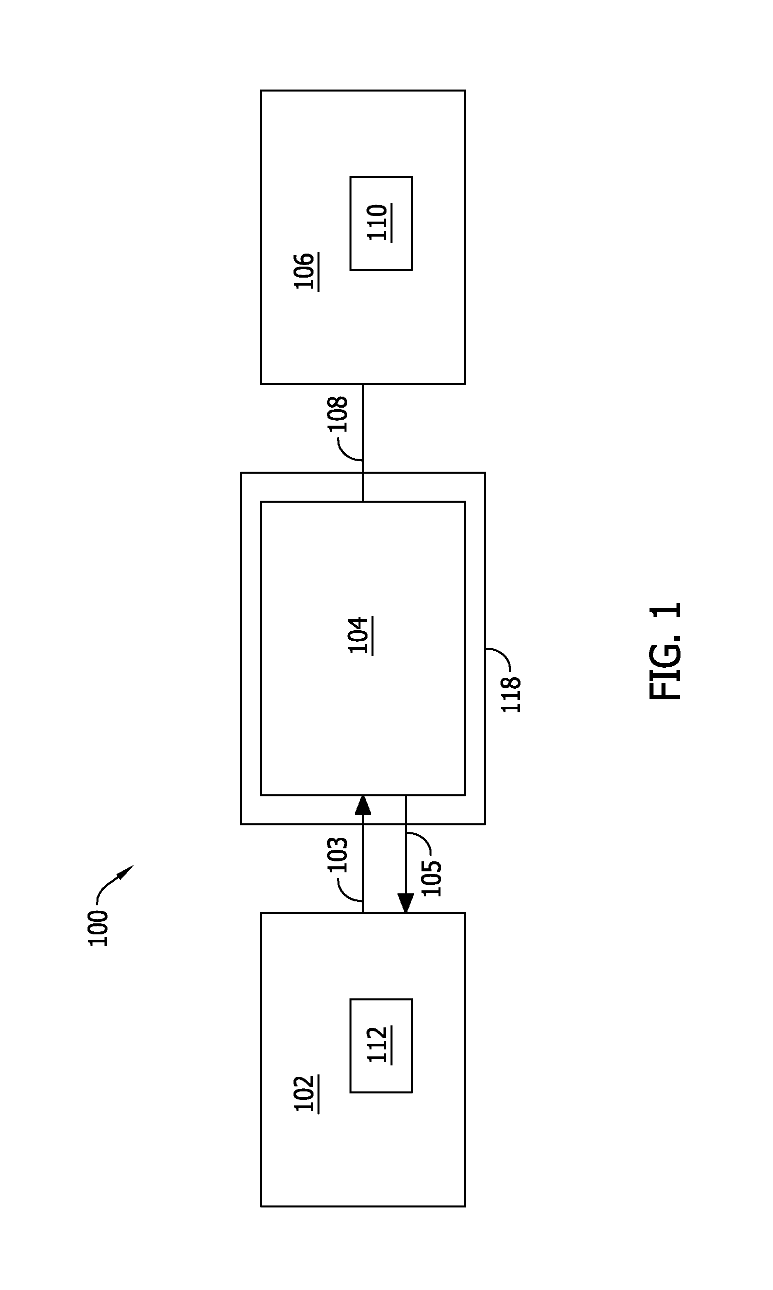
[0018]FIG. 1 is a block diagram of an example system 100 that includes a motor controller 102 coupled to a motor 104. Motor controller 102 transmits instructions 103 to motor 104 to control an operation of motor 104, and receives feedback 105 from motor 104 to determine the operational status of motor 104. In some implementations, motor controller 102 is incorporated within motor 104. Motor 104 may be an electric motor and, in some implementations, is an electric variable speed motor, such as an electronically commutated motor (ECM). Motor 104 drives a load 106 that includes a fluid-moving element 110, such as a fan, a blower wheel, a compressor, or an impeller. Motor 104 is coupled to fluid-moving element 110 by a shaft 108. Accordingly, system 100 may be used, for example, in a heating, ventilation, and air conditioning (HVAC) system, or, in other implementations, in an aquatic system, such as a pool or spa. Motor controller 102 includes a computing device 112 configured to enable...


PUM


Abstract

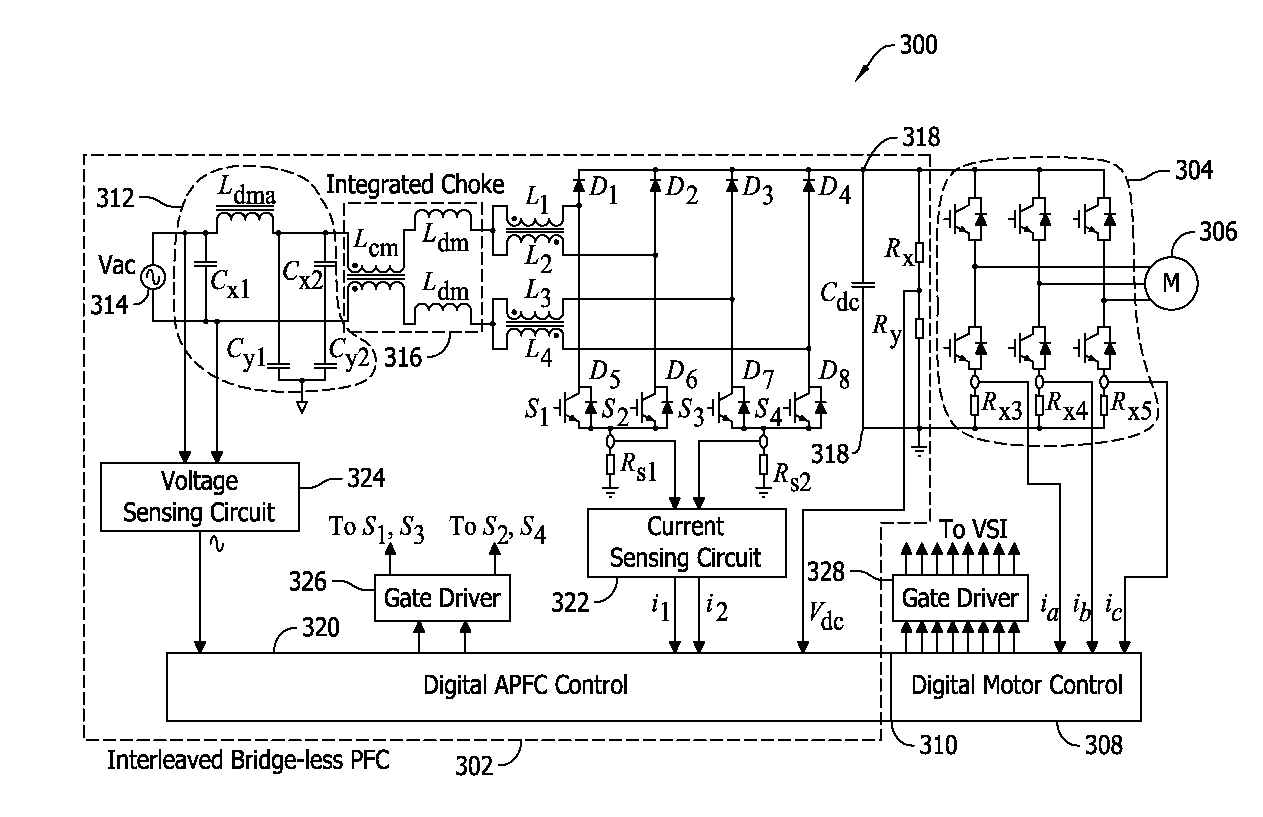
An interleaved bridgeless power factor correction (PFC) converter-based motor drive system is provided. The system includes a first inductor coupled to a second inductor. The coupled first and second inductors are coupled to a first input configured to be coupled to a first line of an alternating current (AC) power supply. The system also includes a third inductor coupled to a fourth inductor. The coupled third and fourth inductors are coupled to a second input configured to be coupled to a second line of the AC power supply. The system further includes a digital active power factor correction (PFC) controller configured to cause current in at least one of the coupled first and second inductors and the coupled third and fourth inductors to be interleaved.

Description

BACKGROUND[0001]The field of the disclosure relates generally to motor controllers, and more particularly, to systems and methods for controlling a motor.[0002]Motor drive systems in heating, ventilation, air-conditioning (HVAC) applications usually utilize diode / rectifier-based passive AC-DC stages and large aluminum electrolytic capacitors (i.e., 1000˜2000 microfarads) to maintain a substantially constant DC voltage. In general, pulsed current is generated from an AC power line, leading to a lower power factor (PF). Simultaneously, low frequency harmonic currents enter the electrolytic capacitors, causing increased temperatures and reduced life span. Moreover, a large dc-link capacitance usually leads to high inrush current during power-up. Passive inrush current limiters (i.e., negative temperature coefficient (NTC) thermistors) are typically provided in the AC power line to reduce inrush current, however, they also reduce overall system efficiency and long-term reliability. Also...

Claims


Application Information

Patent Timeline
IPC IPC(8): H02P6/00H01F17/04H02M1/42
CPCH02P6/002H02M1/4225H01F2017/0093H01F17/04H02M1/4266H02M1/126H02M3/1584H02P2201/09H02P2201/15Y02B70/10H02M1/123H02M1/0085H02P6/28
Inventor LI, MINGYI, PEIZHONGBECERRA, ROGER CARLOSCHRETIEN, LUDOVIC ANDRE
Owner REGAL BELOIT AMERICA
Learn More