

Self-Mobile Robot Laser-Guided Travel Operating System and Control Method Therefor
a self-moving, laser-guided technology, applied in the direction of computer control, program control, instruments, etc., can solve the problems of affecting the the inability to control the horizontal the mechanism may only allow the vertical movement of the robot, so as to achieve compact system structure, improve the concentrating performance of the laser, and improve the effect of concentrating performan
- Summary
- Abstract
- Description
- Claims
- Application Information
AI Technical Summary
Benefits of technology
Problems solved by technology
Method used
Image

Examples
first embodiment
The First Embodiment
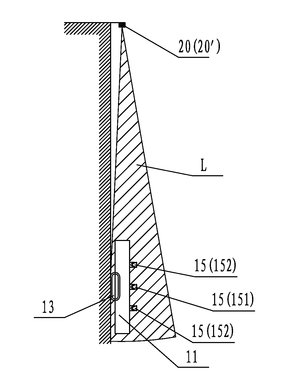
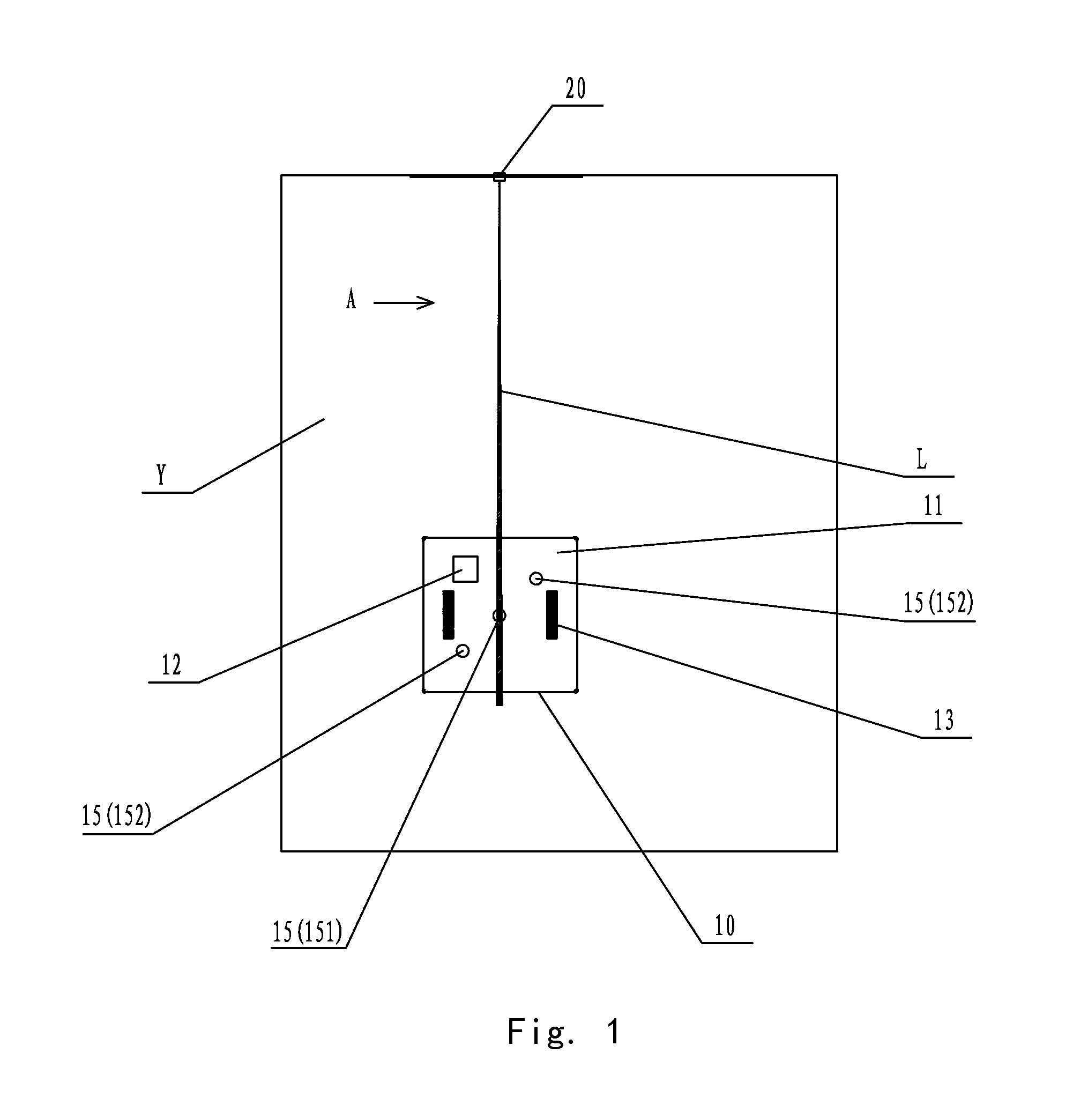
[0048]FIG. 1 is an overall schematic structure drawing of the first embodiment of the present invention, and FIG. 2 is a diagram viewing from the direction A in FIG. 1. As shown in FIG. 1 by reference to FIG. 2, the first embodiment of the present invention provides a laser-guided walking operation system for a self-moving robot comprising a self-moving robot 10 and a laser beam transmitter 20. Specifically, the self-moving robot 10 comprises a machine body 11 on which a control mechanism 12 and a walking mechanism 13 are provided. The laser beam transmitter 20 is provided at an edge of operation region Y of the self-moving robot 10 and laser receivers 15 are provided on the machine body 11 correspondingly. The control mechanism 12 controls the walking mechanism 13 so that the self-moving robot 10 may perform walking operation along a linear path guided by a laser beam signal transmitted by the laser beam transmitter 20 in the operation region Y. According to dif...
second embodiment
The Second Embodiment
[0082]FIG. 9 is a schematic structure drawing of a second embodiment of the present invention. As shown in FIG. 9, the present embodiment and the first embodiment only differ in the setting position of the laser receiver 15 on the top of machine body 11 of the self-moving robot 10. By comparison with FIG. 1 in the first embodiment, there are three laser receivers provided at equal interval substantially along a diagonal of the top surface of machine body 11 of the self-moving robot 10, and the direction of their arrangement is upper right-center-lower left. As shown in FIG. 9, in the present embodiment, there are also three laser receivers provided at equal interval substantially along a diagonal of the top surface of machine body 11 of the self-moving robot 10, and the direction of their arrangement is upper left-center-lower right. The laser receivers of the present embodiment are the same as that in the first embodiment, which are Omni-directional laser recei...
third embodiment
The Third Embodiment
[0084]FIG. 10 is a schematic structure drawing of a third embodiment of the present invention. As shown in FIG. 10, in the present embodiment, there are also three laser receivers 15, however, they are provided horizontally at equal interval along the middle line of the top surface of machine body 11 of the self-moving robot 10. The laser receivers of the present embodiment are the same as that of the first embodiment, which are Omni-directional laser receivers 15′.
[0085]The other technical features of the present embodiment are the same as those of the first embodiment; please refers to the first embodiment for detailed description which will be omitted here.
PUM
 Abstract
Description
Claims
Application Information