Internal combustion engine control apparatus

Active Publication Date: 2016-03-24
MITSUBISHI ELECTRIC CORP
View PDF17 Cites 19 Cited by
  • Summary
  • Abstract
  • Description
  • Claims
  • Application Information

AI Technical Summary

Benefits of technology

[0011]According to one embodiment of the present invention, by measuring the discharge voltage of the spark plug based on the time duration in which the voltage of the primary coil is above the predetermine

Problems solved by technology

When a compression ratio is increased, however, a pressure in a spark discharge gap in a spark plug is increased to disadvantageously increase a discharge voltage of the spark plug.
Thus, large spark energy is required to ignite the air-fuel mixture.
When the spark energy increases, electrodes of the spark plug are likely to wear.
Accordingly, there is a fear in that the discharge voltage of the spark plug exceeds a dielectric withstand voltage to cause dielectric breakdown of the spark plug.
Moreover, when the discharge voltage of the spark plug exceed

Method used


Image

  • Internal combustion engine control apparatus
  • Internal combustion engine control apparatus
  • Internal combustion engine control apparatus

Examples


first embodiment

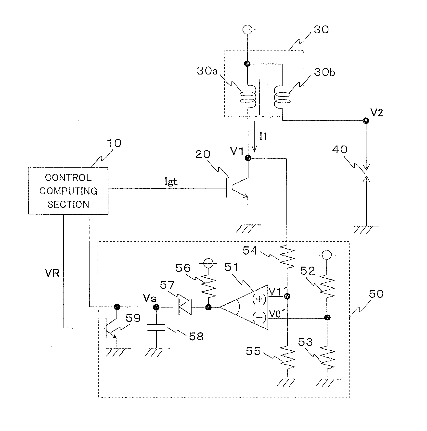
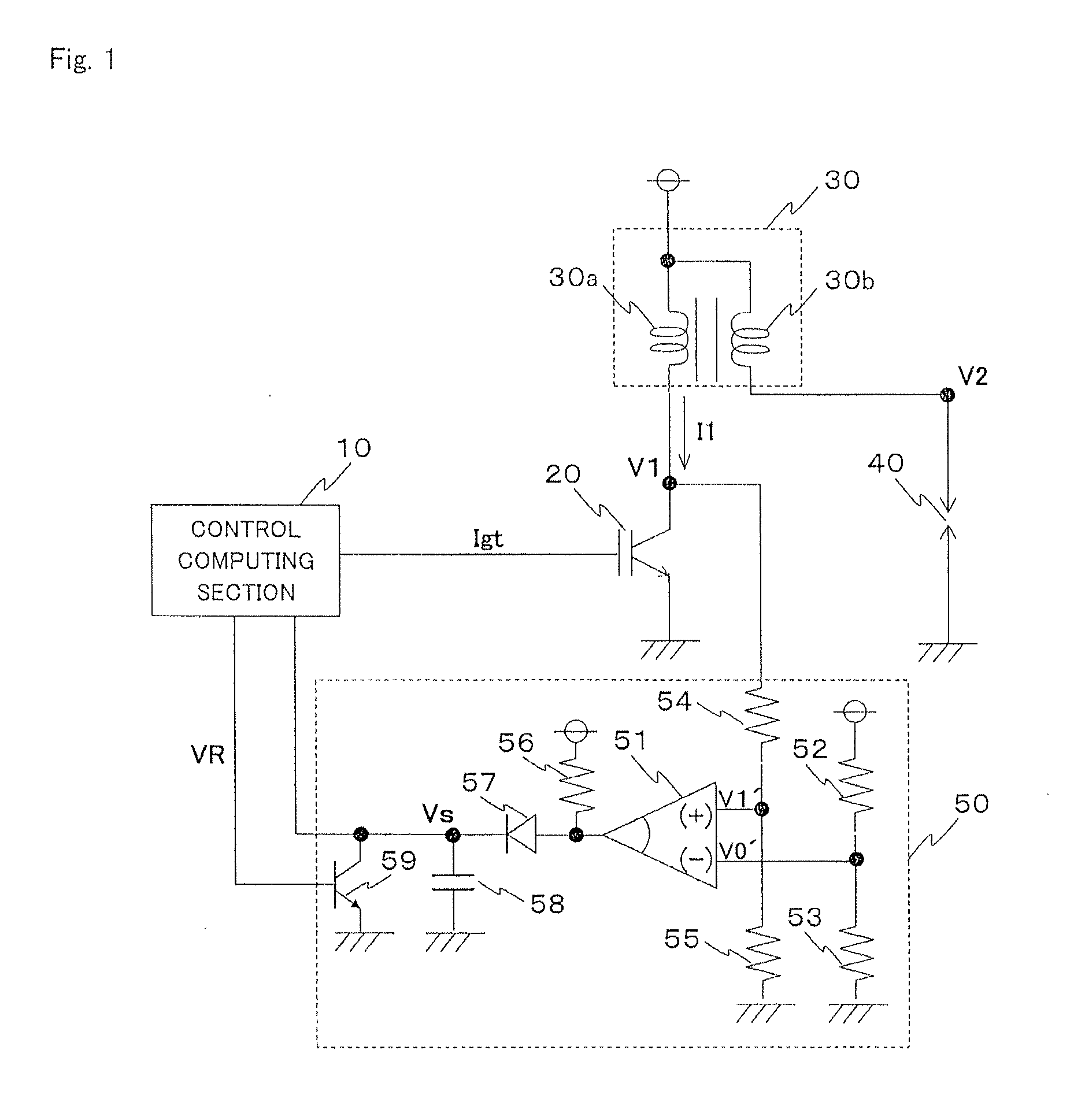
[0021]FIG. 1 is an exemplary diagram of a circuit configuration of an internal combustion engine control apparatus according to a first embodiment of the present invention. The internal combustion engine control apparatus according to the first embodiment includes a control computing section 10, a first switch element 20, an ignition coil 30, a spark plug 40, and a voltage detecting circuit 50. As the control computing section 10, an engine control unit (ECU) for a vehicle is used.

[0022]The ignition coil 30 includes a primary coil 30a and a secondary coil 30b which are magnetically coupled to each other so as to generate a spark discharge in a spark discharge gap in the spark plug 40. The first switch element 20 is turned on and off based on a control signal (hereinafter referred to as “Igt signal”) from the control computing section 10 to control a flow (ON) and interruption (OFF) of a primary coil current I1.

[0023]The voltage detecting circuit 50 includes a comparator 51, voltage-...

second embodiment

[0054]FIG. 7 is an exemplary diagram of a circuit configuration of an internal combustion engine control apparatus according to a second embodiment of the present invention. The internal combustion engine control apparatus illustrated in FIG. 7 differs from that illustrated in FIG. 1 according to the first embodiment described above in that a regulator circuit 60 for regulating the operation of the voltage detecting circuit 50 is further provided. The remaining configuration is the same as that illustrated in FIG. 1.

[0055]The regulator circuit 60 includes comparators 61 and 62, and resistors 63, 64, and 65. The regulator circuit 60 regulates the voltage detecting circuit 50 of the first embodiment described above so that the voltage detecting circuit 50 responds only to the first spark discharge but not to the subsequent spark discharges even in the case where the spark discharge is caused in the spark plug 40 for a plurality of times. With the regulator circuit 60, the discharge vo...


PUM


Abstract

An internal combustion engine control apparatus includes: an ignition coil including a primary coil and a secondary coil that are magnetically coupled to each other; a first switch element for turning on and off a current to the primary coil; and a spark plug, for igniting an air-fuel mixture in an internal combustion engine by using a spark discharge caused by switching the first switch element from the ON state to the OFF state. The internal combustion engine control apparatus is configured to: determine occurrence of one of an abnormality in a discharge voltage and a misfire of the spark plug, when the calculated time duration in which a voltage of the primary coil after the switching of the first switch element from the ON state to the OFF state is above a predetermined comparison reference voltage does not fall within an allowable range.

Description

BACKGROUND OF THE INVENTION[0001]1. Field of the Invention[0002]The present invention relates to an internal combustion engine control apparatus including a spark plug which is driven by a current interruption-type ignition circuit, for igniting an air-fuel mixture in an internal combustion engine, in particular, a technology of detecting an abnormality in a discharge voltage and a misfire of the spark plug.[0003]2. Description of the Related Art[0004]In recent years, a high compression-ratio technology and a gasoline in-cylinder direct injection technology become more and more important in order to improve fuel efficiency of an internal combustion engine (gasoline engine). When a compression ratio is increased, however, a pressure in a spark discharge gap in a spark plug is increased to disadvantageously increase a discharge voltage of the spark plug. Moreover, when the gasoline in-cylinder direct injection is performed, a difference in density is likely to be generated in an air-f...

Claims


Application Information

Patent Timeline
IPC IPC(8): F02P11/06F02D37/02F02P9/00F02P11/02F02P15/00F02P17/10
CPCF02P11/06F02P11/02F02D37/02F02P17/10F02P9/002F02P15/006F02P3/0414F02P3/055F02P17/12
Inventor OKUDA, HIROSHI
Owner MITSUBISHI ELECTRIC CORP
Why Eureka
Try Eureka