Optical communication device and optical communication method

a communication device and optical communication technology, applied in the field of optical communication devices and optical communication methods, can solve the problems of increasing the cost and space of equipment placemen

Active Publication Date: 2016-03-24
IND TECH RES INST
View PDF21 Cites 36 Cited by
  • Summary
  • Abstract
  • Description
  • Claims
  • Application Information

AI Technical Summary

Problems solved by technology

Nowadays, the operators place one RoF equipment for each system, which increases the cost and space to place the equipment.

Method used


Image

  • Optical communication device and optical communication method
  • Optical communication device and optical communication method
  • Optical communication device and optical communication method

Examples


Embodiment Construction

[0015]The term “couple” or “coupled” used in the disclosure and the claims may refer to any direct or indirect connection. For example, when describing a first device coupled to a second device, the first device may be connected to the second device directly, or the first device may be connected to the second device indirectly through any other devices, methods, or connection techniques.

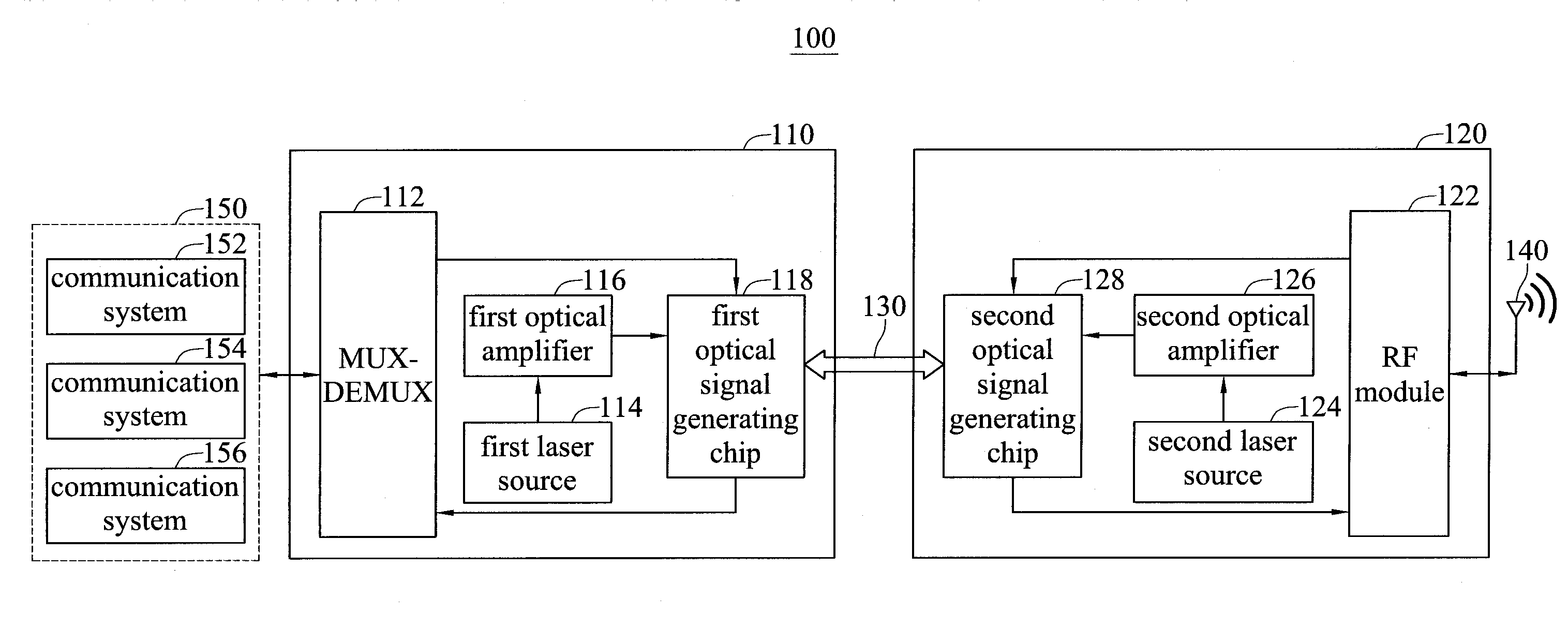
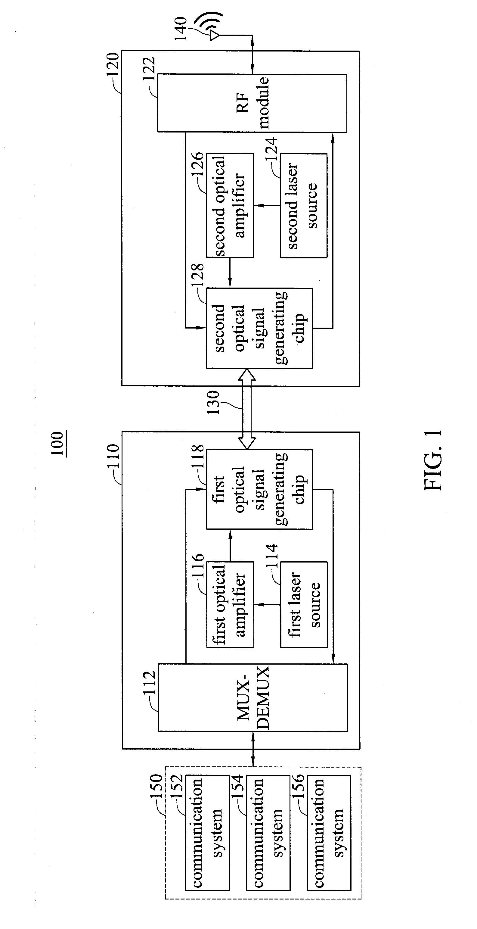
[0016]FIG. 1 is a diagram showing an optical communication system 100 in accordance with an embodiment of the disclosure. The optical communication system 100, for example, is a radio-over-fiber (RoF) communication system which supports a plurality of communication systems. The optical communication system 100 includes a head-end unit (HEU) 110 and a remote access unit (RAU) 120. The head-end unit 110 may be an optical communication device. The head-end unit 110 includes a multiplexer-demultiplexer (MUX-DEMUX) 112, a first laser source 114, a first optical amplifier 116, and a first optical signal ge...


PUM


Abstract

An optical communication device and an optical communication method are provided. The optical communication device includes a laser source, an optical amplifier, and an optical signal generating chip. The laser source generates a laser beam. The optical amplifier is coupled to the laser source and amplifies light intensity of the laser beam in a specific wavelength band. The optical signal generating chip includes a micro-resonator and a modulation module. The micro-resonator is coupled to the optical amplifier and generates a multi-wavelength frequency comb according to the amplified laser beam. The modulation module is coupled to the micro-resonator and modulates a communication signal set to generate a plurality of optical modulated signals according to the multi-wavelength frequency comb.

Description

CROSS-REFERENCE TO RELATED APPLICATION[0001]This application claims foreign priority under 35 U.S.C. §119(a) to patent application Ser. No. 10 / 313,2407, filed on Sep. 19, 2014, in the Intellectual Property Office of Ministry of Economic Affairs, Republic of China (Taiwan, R.O.C.), the entire content of which Patent Application is incorporated herein by reference.TECHNICAL FIELD[0002]The technical field is related to an optical communication device and an optical communication method.BACKGROUND OF THE INVENTION[0003]The data traffic amount grows along with the growing development of mobile Internet and multi-media applications. It is going to be an era of fourth generation (4G) communication. For the placement of 4G base stations, in addition to the consideration of the coverage areas of the large base stations, small equipment may be used to extend the coverage areas of the base stations in some areas where the signal quality is not good or in some areas which is not suitable for th...

Claims


Application Information

Patent Timeline
Patent Type & Authority Applications(United States)
IPC IPC(8): H04B10/2575H04B10/50H04J14/02
CPCH04B10/25752H04J14/02H04B10/506H04B10/504H04B10/25758
Inventor LIU, TZE-ANHSU, PO-ERCHEN, HSIN-FENG
Owner IND TECH RES INST
Why Eureka
Try Eureka