
Data transmission apparatus and method for transmitting data in delay-insensitive data transmission method supporting handshake protocol

a data transmission and delay-insensitive technology, applied in the field of data transmission apparatus and method for transmitting data in a delay-insensitive data transmission method supporting a handshake protocol, can solve the problems of increasing the number of wires for data transmission, increasing the number of clocks, and increasing the complexity of the wiring structure of transmission lines designed in one chip

Active Publication Date: 2016-03-24
ELECTRONICS & TELECOMM RES INST
View PDF1 Cites 0 Cited by
  • Summary
  • Abstract
  • Description
  • Claims
  • Application Information

AI Technical Summary

Benefits of technology

The patent aims to offer a device and method for reducing the number of wires used for data transmission in a system on chip (SoC) design, specifically a GALS system. This simplifies the process of data transmission and reduces the complexity of the system.

Problems solved by technology

Recently, with the further development of semiconductor process technology and integrated circuit design technology, the number of devices which can be integrated in one chip is gradually increasing, and as a result, the wiring structure of transmission lines designed in one chip is becoming more complicated.
Meanwhile, when a synchronous design using a global clock is applied to integrated circuit systems implemented in the SoC scheme, clock skew and jitter are caused by an increase in clock speed, a transmission delay of data is caused by an increase in the number and the lengths of transmission lines, and so on.
However, to implement such an asynchronous design, the design of an overall circuit becomes complicated, and a function of computer aided design (CAD) tools for an asynchronous design is insufficient.
However, since 2N+1 wires are required for N-bit data transmission, performance, power consumption, and design complexity of the LEDR are degraded due to the increased number of wires.
As a result, the complexity of a receiver circuit remarkably increases, and thus the number of wires that can be reduced is limited.
Also, in a trend toward lowering a supply voltage in an integrated circuit, the current-mode multi-valued logic circuit technology for expressing a plurality of states using a voltage which is used in the previous literature may degrade a noise margin characteristic of a voltage in a receiver circuit.
Further, the previous literature does not support a handshake protocol necessary for DI data transmission, and thus cannot be applied to a GALS system.
However, according to the two data transmission methods using a current-mode circuit (Korean Patent Application Nos. 10-2004-0011299 and 10-2006-0119056), N inputs are encoded with N+1 wires, and thus the two data transmission methods are not satisfactory in terms of a reduction in the number of wires.
This may make it very difficult to determine a delay time of a delay element, and in some cases (the largest time difference between an input request signal and a data signal > the shortest period of request signals), it may not be possible to find a satisfactory delay time of a delay element.
This means that it is not possible to ensure the functionality of an encoder.
Also, the previous literature (Korean Patent Application No. 10-2008-0119279) does not proposes a method of reducing the latency of data transmission through a long wire, such as buffer insertion, used in binary data transmission based on a voltage mode.
In other words, implementation is complicated.
Further, according to the previous literature (Korean Patent Application No. 10-2008-0119279), N inputs are encoded with N+1 wires, like in the above-described previous literature, and thus the previous literature (Korean Patent Application No. 10-2008-0119279) is not satisfactory in terms of a reduction in the number of wires.

Method used


Image

  • Data transmission apparatus and method for transmitting data in delay-insensitive data transmission method supporting handshake protocol
  • Data transmission apparatus and method for transmitting data in delay-insensitive data transmission method supporting handshake protocol
  • Data transmission apparatus and method for transmitting data in delay-insensitive data transmission method supporting handshake protocol

Examples


Embodiment Construction

[0051]Exemplary embodiments of the present invention will be described in detail below with reference to the accompanying drawings. While the present invention is shown and described in connection with exemplary embodiments thereof, it will be apparent to those skilled in the art that various modifications can be made without departing from the spirit and scope of the invention.

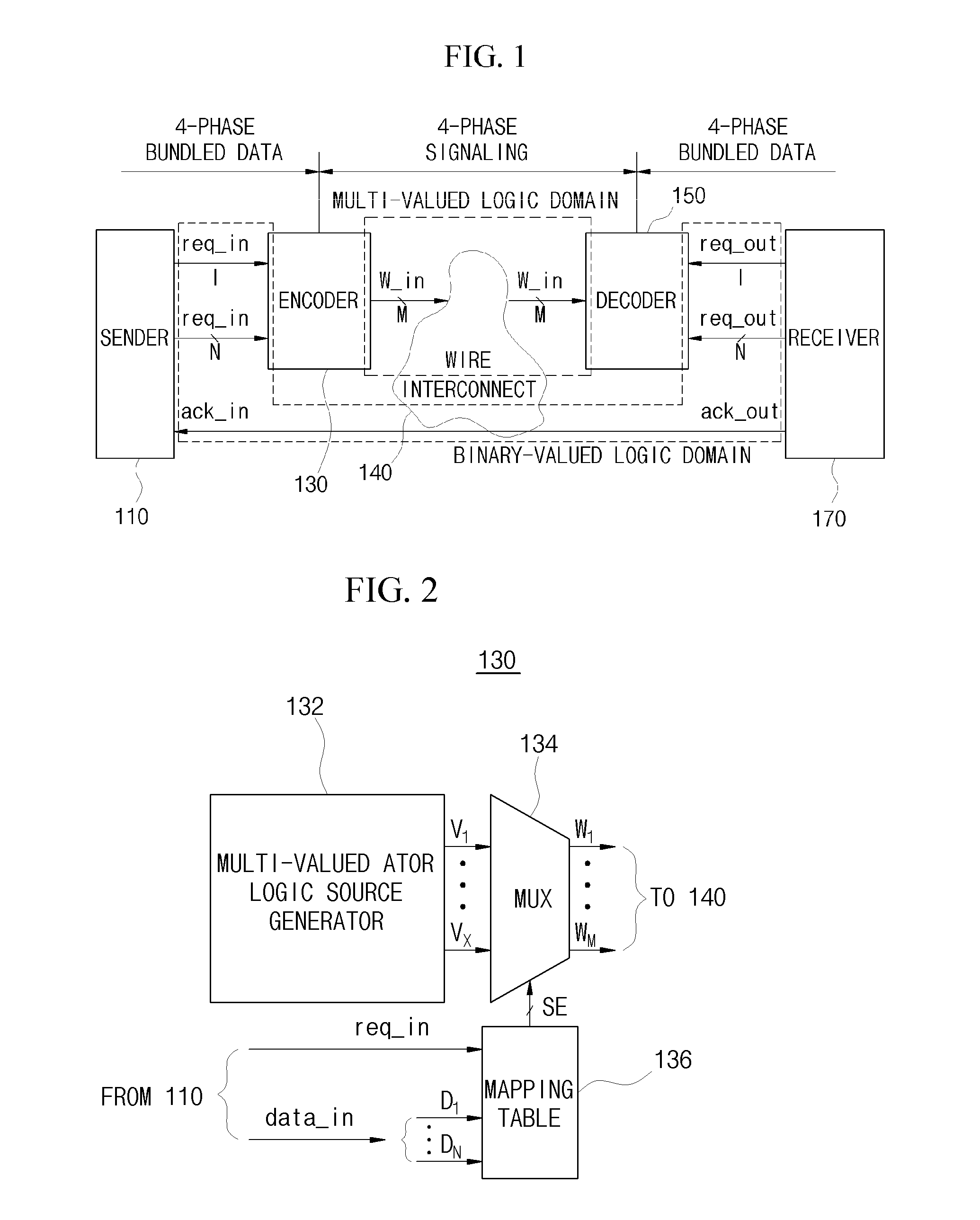
[0052]FIG. 1 is a block diagram showing a data transmission environment according to an exemplary embodiment of the present invention.

[0053]Referring to FIG. 1, a data transmission apparatus 100 according to an exemplary embodiment of the present invention includes a sender 110 and a receiver 170 which exchange data with the outside thereof using handshake signals based on 4-phase signaling.

[0054]Also, the data transmission apparatus 100 according to an exemplary embodiment of the present invention includes an encoder 130 and a decoder 150 for interfacing between the sender 110 and the receiver 170.

[0055]The ...


PUM


Abstract

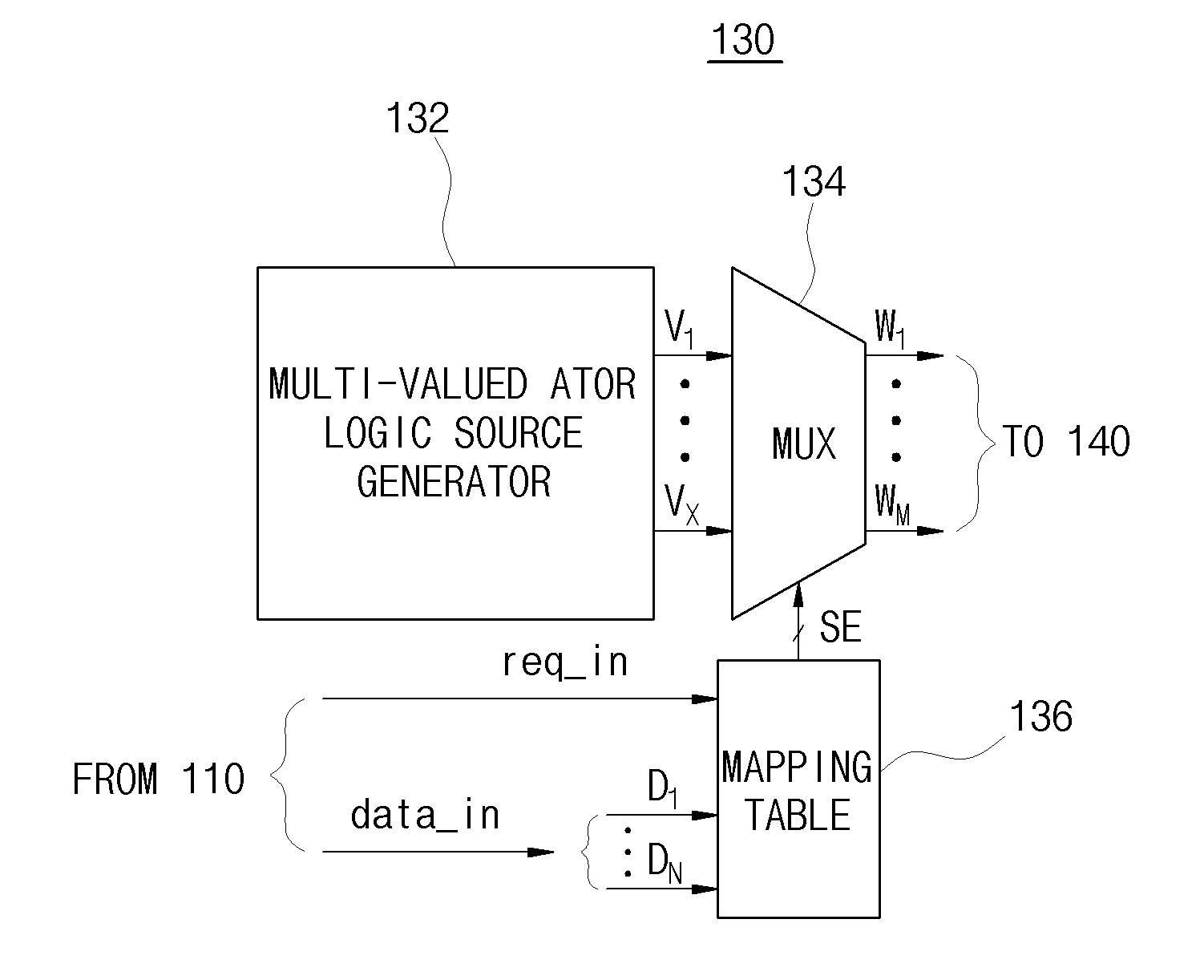
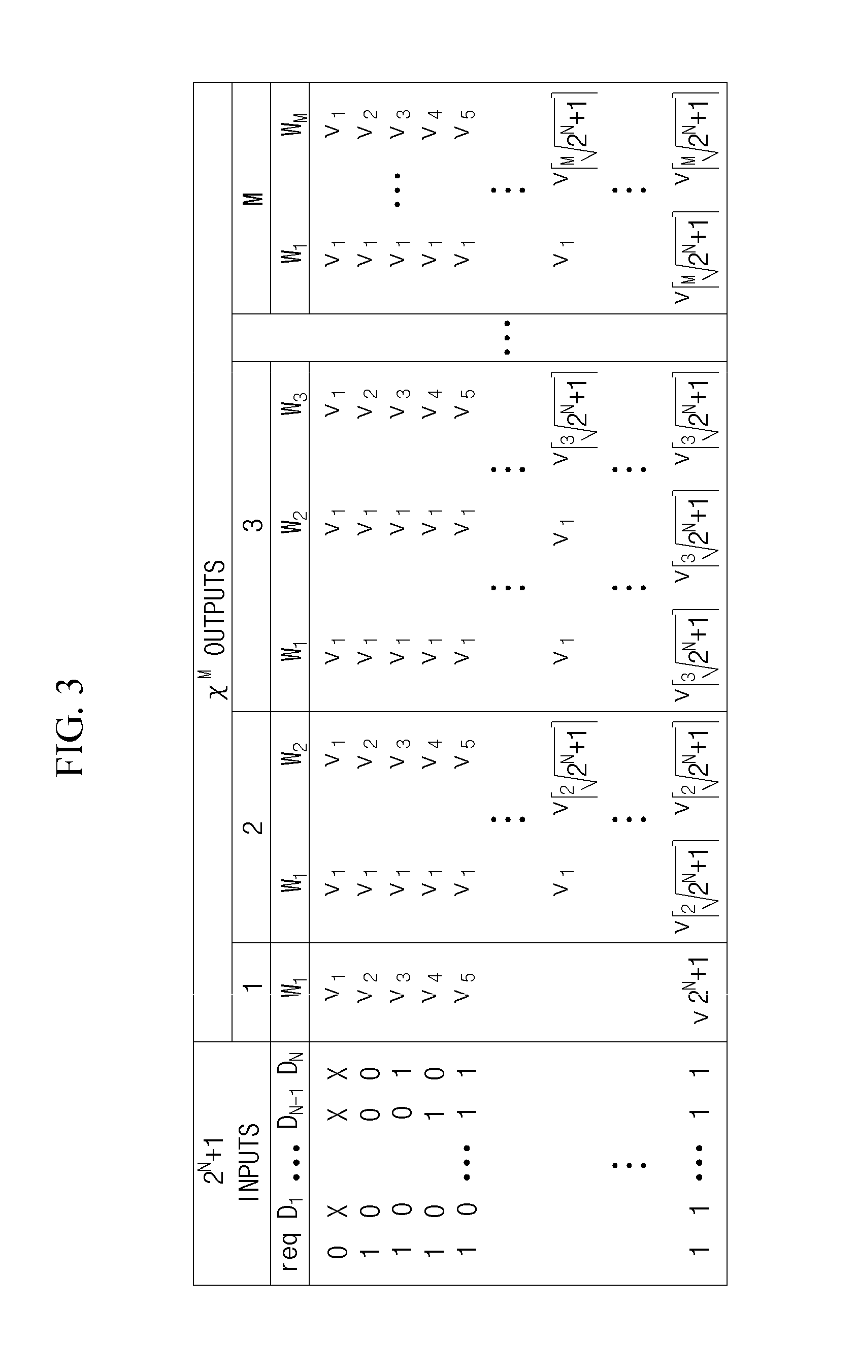
Provided are a data transmission apparatus and method for transmitting data in a Delay-Insensitive (DI) data transmission method supporting a handshake protocol. The data transmission apparatus includes a sender which outputs a binary-valued logic signal based on binary-valued logic, and an encoder which encodes the binary-valued logic signal input through input wires into a multi-valued logic signal based on multi-valued logic and transmits the encoded multi-valued logic signal to a decoder through output wires. Here, the encoder includes a mapping table which stores input variables including the number of input wires and the number of output wires smaller than the number of input wires and the multi-valued logic signal corresponding to the input variables, and encodes the binary-valued logic signal into the multi-valued logic signal with reference to the mapping table.

Description

CROSS-REFERENCE TO RELATED APPLICATION[0001]This application claims priority to and the benefit of Korean Patent Application No. 10-2014-0127830, filed on Sep. 24, 2014, the disclosure of which is incorporated herein by reference in its entirety.BACKGROUND[0002]1. Field of the Invention[0003]The present invention relates to a data transmission apparatus and method for transmitting data in a delay-insensitive (DI) data transmission method supporting a handshake protocol, and more particularly, to a data transmission apparatus and method capable of reducing power consumption and complexity caused by a large number of wires in a large-scale system on chip (SoC) design, such as a globally asynchronous locally synchronous (GALS) system.[0004]2. Discussion of Related Art[0005]Currently, due to the development of semiconductor process technology and integrated circuit design technology, integrated circuit systems are designed in an SoC scheme implemented in units of chips.[0006]Recently, w...

Claims


Application Information

Patent Timeline
Patent Type & Authority Applications(United States)
IPC IPC(8): H04L1/18H04L29/06
CPCH04L65/607H04L1/1893H04L25/4917H04L25/00
Inventor OH, MYEONG, HOON
Owner ELECTRONICS & TELECOMM RES INST
Learn More