Punch press

a technology of punch press and punch plate, which is applied in the field of punch plate, can solve the problems of substantial time required, difficult replacement work, and substantial inability to achieve replacement, and achieve the effect of simple structure and easy and efficient replacemen

Inactive Publication Date: 2016-03-31
MURATA MASCH LTD
View PDF6 Cites 2 Cited by
  • Summary
  • Abstract
  • Description
  • Claims
  • Application Information

AI Technical Summary

Benefits of technology

[0008]In view of the foregoing problems and inconveniences inherent in the prior art, preferred embodiments of the present invention provide a punch press that is simple in

Problems solved by technology

This replacement work is difficult to accomplish because a die placement section of the die holder is hidden beneath the upper turret and is therefore not readily available within the sight.
In particular, in the case of the die holder in which a plurality of dies are supported having been juxtaposed relative to each other in a radial direction of the lower turret, the attendant worker's hand would hardly reach, from below the lower turret, the die situated at a far deep side as viewed from

Method used


Image

  • Punch press
  • Punch press
  • Punch press

Examples


Embodiment Construction

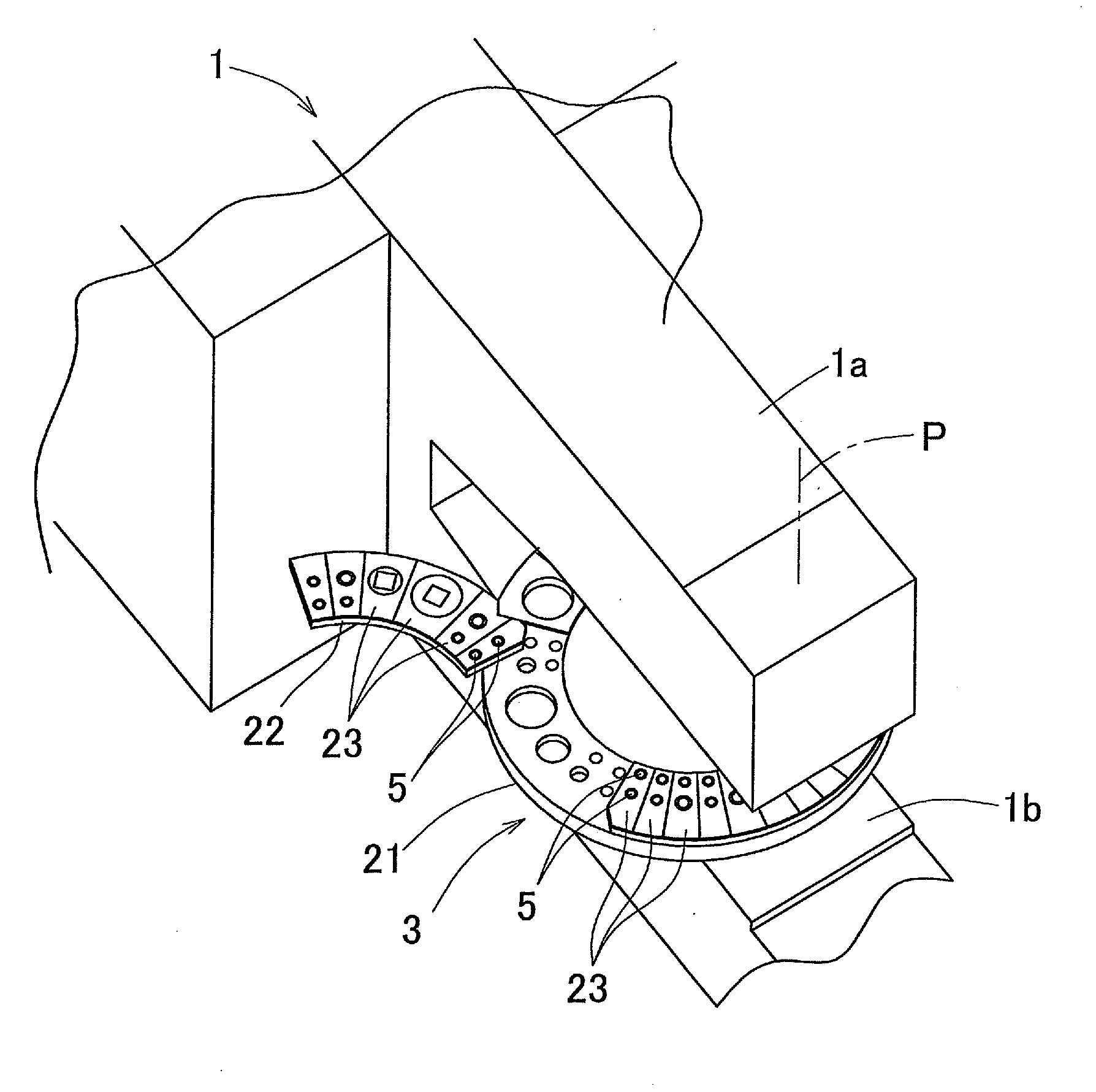
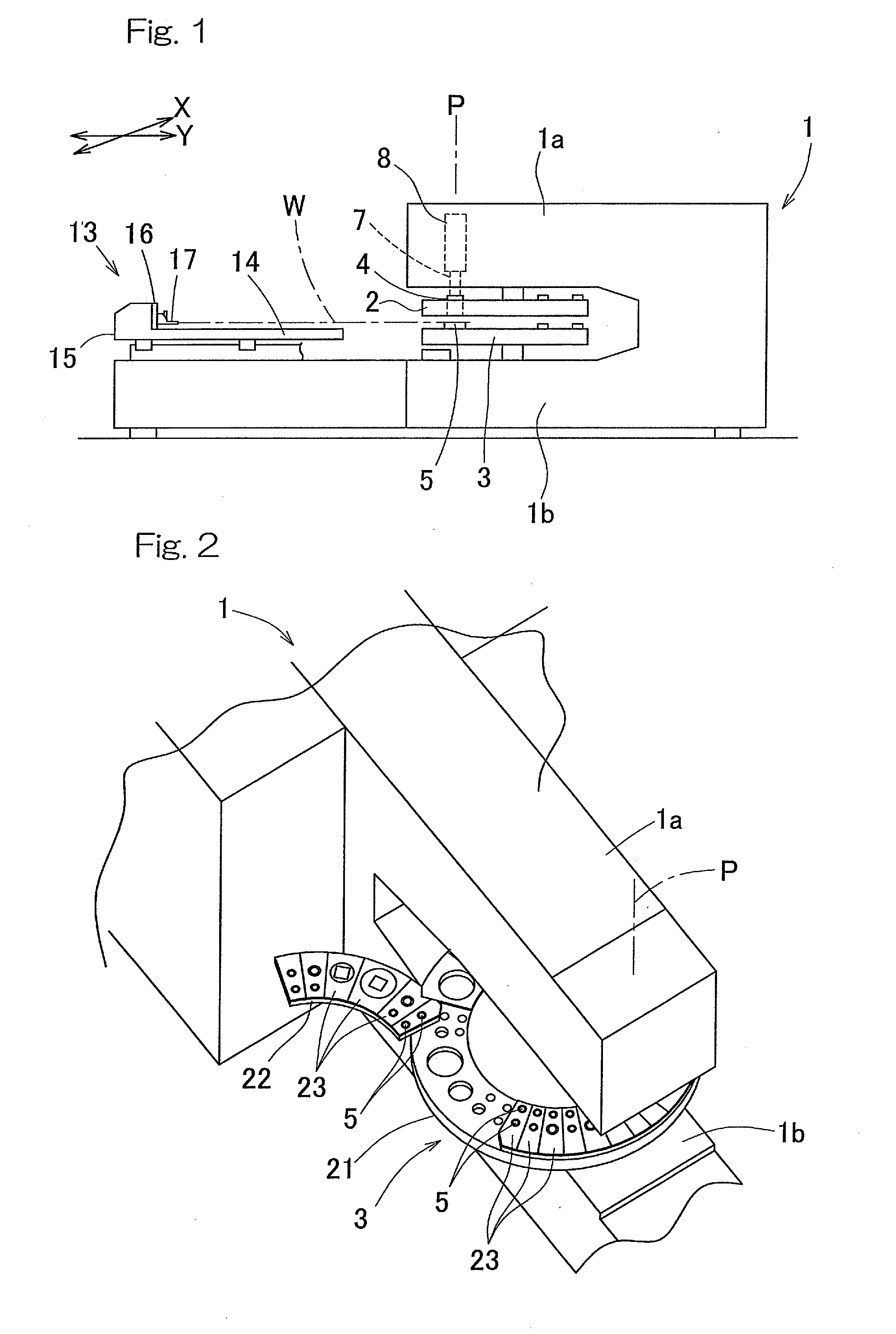
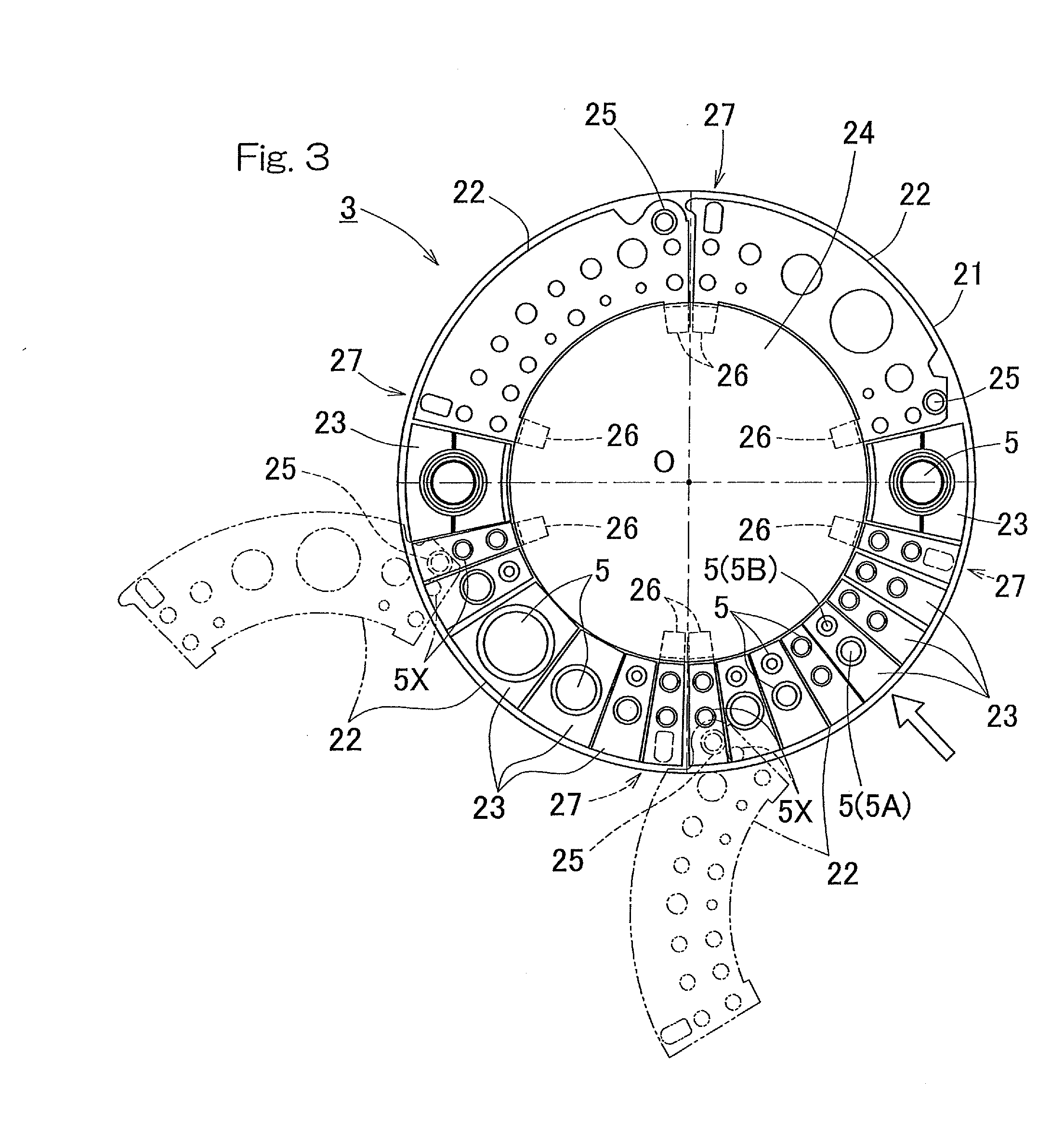
[0027]The present invention will now be described in detail in connection with a preferred embodiment thereof with reference to the accompanying drawings. In particular, FIG. 1 is a schematic side view of a punch press in its entirety according to a preferred embodiment of the present invention, and FIG. 2 is a perspective view showing the punch press with a portion thereof removed. The illustrated punch press preferably is of a type having upper and lower turrets 2 and 3, for example. It is to be noted that the upper turret 2 is not shown in FIG. 2 for the sake of brevity. Each of the upper and lower turrets 2 and 3 is of a substantially flat round configuration, and those upper and lower turrets 2 and 3 are supported respectively by upper and lower horizontal frame sections 1a and 1b of a press frame structure 1 for rotation coaxially about associated vertical shafts. The upper turret 2 defines an integrated punch support body and has a plurality of punches 4 arranged in line alon...


PUM


Abstract

A punch press includes a punch support body, on which a plurality of punches are mounted, and an integrated die support body positioned below the integrated punch support body and including a plurality of dies mounted thereon to perform a punching process in cooperation with the punches. The plurality of the dies are juxtaposed along a rim of the integrated die support body. The integrated die support body includes an integrated die support main body and an in-and-out moving body that enables at least a portion thereof to assume a condition emerging out of the rim of the integrated die support body while its connection with the integrated die support main body is retained. Some of the dies disposed in the integrated die support body are disposed in the in-and-out moving body.

Description

CROSS REFERENCE TO THE RELATED APPLICATION[0001]This application is based on and claims Convention priority to Japanese patent application No. 2013-109586, filed May 24, 2013, the entire disclosure of which is herein incorporated by reference as a part of this application.BACKGROUND OF THE INVENTION[0002]1. Field of the Invention[0003]The present invention relates to a punch press which performs a punching process on a sheet material and, more particularly, to improvements in die replacement work.[0004]2. Description of the Related Art[0005]By way of example, a turret punch press includes a die holder disposed in a lower turret, which defines an integrated die support body, and a die supported by the die holder, which defines a lower tool. When it comes to replacement of the die, a replacement work is carried out via an attendant worker's hand or a tool inserted between upper and lower turrets. This replacement work is difficult to accomplish because a die placement section of the d...

Claims


Application Information

Patent Timeline
IPC IPC(8): B21D28/12
CPCB21D28/12B21D28/34B21D28/36B21D28/125B21D37/145
Inventor SAKAMOTO, HIROICHI
Owner MURATA MASCH LTD
Why Eureka
Try Eureka