Data center network

a data center network and data center technology, applied in the field of communication networks, can solve the problems of complex computer system operation and maintenance, data center operation and maintenance is typically very expensive, and the complexity of the system is complex

Active Publication Date: 2016-03-31
FIBER MOUNTAIN INC
View PDF1 Cites 43 Cited by
  • Summary
  • Abstract
  • Description
  • Claims
  • Application Information

AI Technical Summary

Benefits of technology

[0019]The present disclosure provides a data center network comprising one or more rows, wherein each row has one or more racks, and wherein each of the one or more racks has at least one network device and at least one top-of-rack network switch, and at least one end-of-row fiber mesh interconnect in communication with each top-of-rack network switch within the same row of the one or more rows, such that each top-of-rack network switch has a direct connection to every other top-of-rack network switch within the same row. In an exemplary embodiment, each top-of-rack network switch comprises a housing having one or more connection panels, and a set of ports, wherein each port within the set of ports is configured to receive data streams from at least one network device within each of the one or more racks, and to transmit data streams to at least one network device within each of the one or more racks, wherein each port in the set of ports includes a connector and at least one transceiver optically coupled to the connector, and wherein the connector is mounted to the one or more connection panels for connecting to the at least one network device and the end-of-row fiber mesh interconnect.
[0020]The present disclosure also provides a data center network, comprising one or more rows, wherein each row has one or more racks, and wherein each of the one or more racks has at least one network device and at least one top-of-rack fiber mesh interconnect, and at least one end-of-row fiber mesh aggregation

Problems solved by technology

Early computer systems were complex to operate and maintain, and required a special environment in which to operate.
However, data centers are typically very expensive to build, operate and maintain, and data center operators are searching for ways to reduce costs while increasing data processing and transmission capabilities, while meeting all reliability requirements.
As networks grow in size, so does the complexity.
This can result in very complex hierarchical switching networks which in turn require considerable pow

Method used


Image

  • Data center network
  • Data center network
  • Data center network

Examples


Embodiment Construction

[0051]In this disclosure, a connection can be a single copper or fiber connection or a duplex connection having a transmit connection and a receive connection. For ease of drafting, reference to a connection or connections includes both a single connection or a duplex connection.

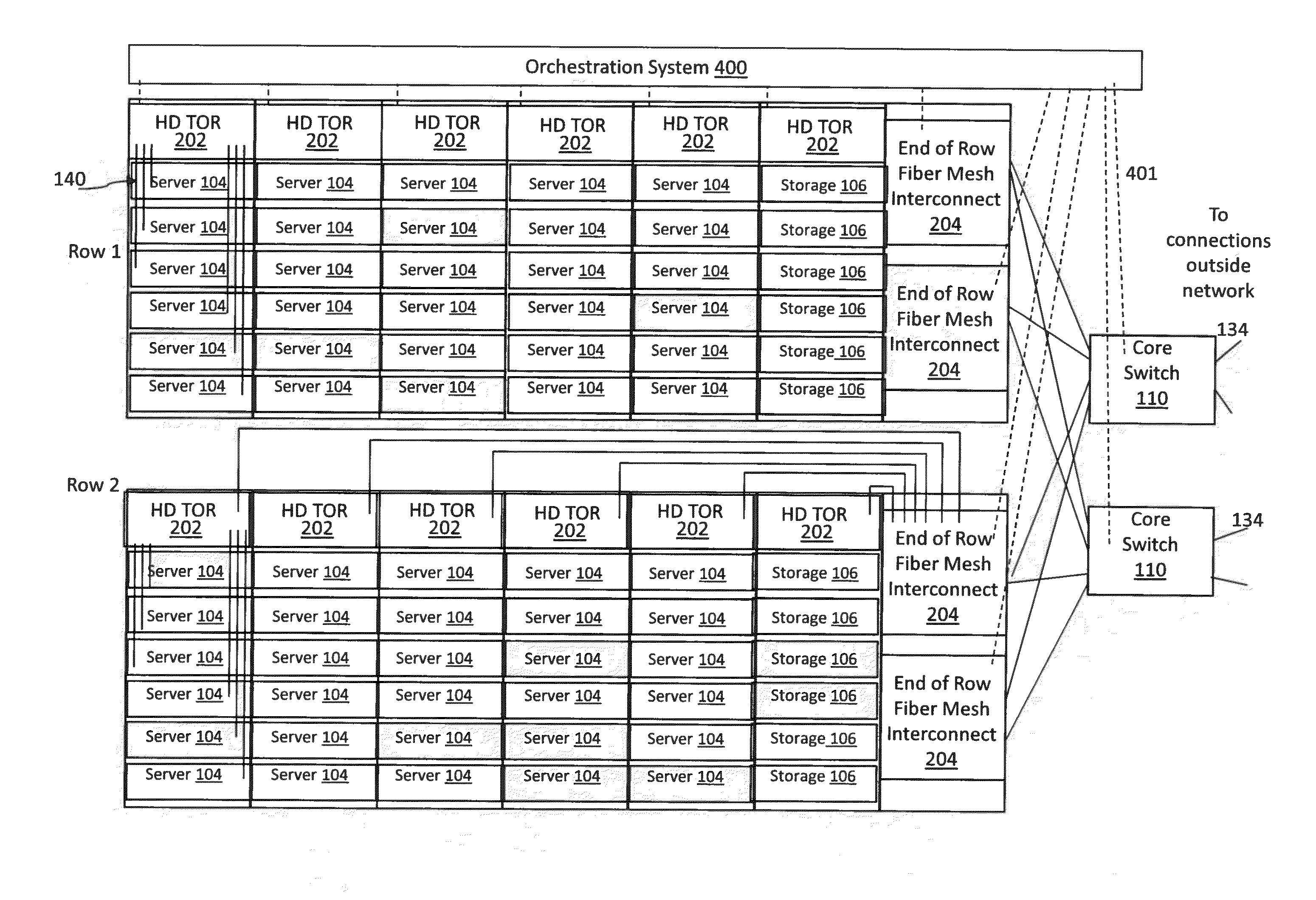
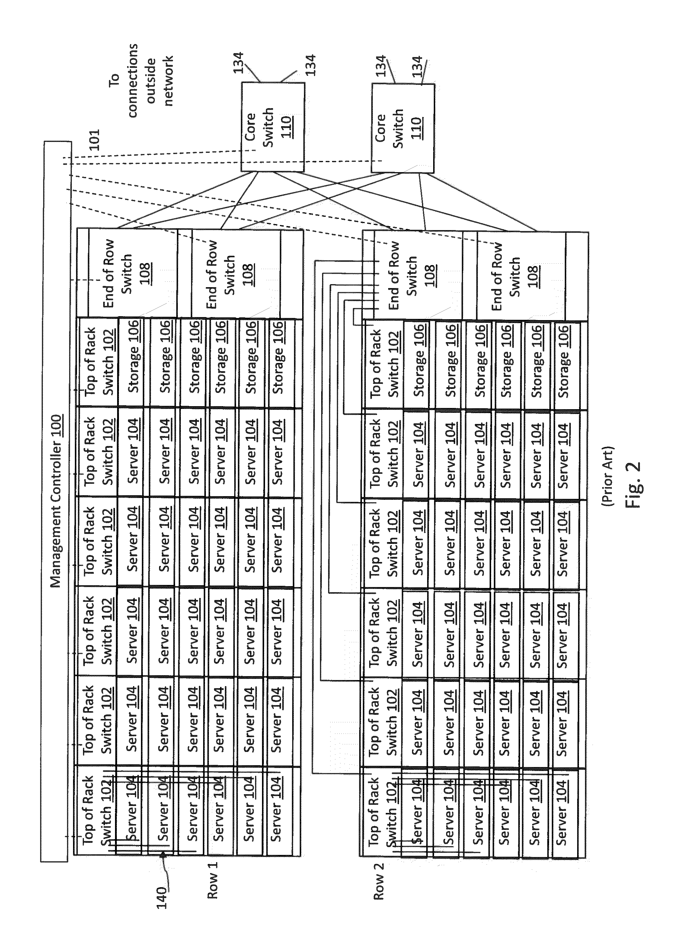
[0052]The data center network of the present disclosure provides a new class of high port density network switches. An example of a high density port network switch is provided in the description in U.S. Provisional Patent Application entitled “System For Increasing Fiber Port Density In Data Center Applications”, Ser. No. 62 / 057,008, filed Sep. 29, 2014, which is incorporated herein in its entirety by reference. Utilizing the high port density network switch elevates the Top of Rack (TOR) switches 102 to High Density Top of Rack (HD TOR) 202 switches, and along with new fiber interconnection methodologies, can be configured as an interconnection fabric, replacing or significantly reducing the need for End o...


PUM


Abstract

The present disclosure provides a data center network having one or more data center rows, where each row has one or more racks, and each rack has one or more network devices, such as servers, storage devices and switches. The rows and racks are interconnected by a fiber interconnect core that reduces the number of switching nodes in the data center network, and reduces the individual path latency, the overall data center network cost, power consumption, and power and cooling requirements.

Description

CROSS-REFERENCE TO RELATED APPLICATIONS[0001]This application claims priority to co-pending U.S. Provisional Application No. 62 / 057,086, filed on Sep. 29, 2014, entitled “Data Center Network,” and to co-pending U.S. Provisional Application No. 62 / 057,008, filed on Sep. 29, 2014, entitled “System for Increasing Fiber Port Density in Data Center Applications” both of which are incorporated herein in their entirety by reference.BACKGROUND ART[0002]1. Field[0003]The present application relates generally to communication networks, and more particularly to data center networks with improved interconnections and improved interconnection management.[0004]2. Description of the Related Art[0005]Communication networks have a long history, evolving from single transmission lines and manual switching, to early multi-line automatic electro-mechanical switching systems, to more recent electronic and optical transmissions across many lines or fibers using electronic or optical switching systems.[00...

Claims


Application Information

Patent Timeline
IPC IPC(8): G02B6/44H04Q11/00
CPCG02B6/4452G02B6/4446H04Q2011/0083H04Q11/0066H04Q2011/0052H04Q11/0005
Inventor RAZA, MOHAMMAD, H.STONE, DAVID, G.LORENZO, ARISTITOPLANTE, RONALD, M.LAGANA, JOHN, R.LY, PHUC, MINH
Owner FIBER MOUNTAIN INC
Why Eureka
Try Eureka