Camera filter frame and camera filter unit
a filter frame and camera technology, applied in the direction of camera filters, mountings, instruments, etc., can solve the problems of damage to the surface of the filter frame, the optics of the filter is not securely gripped by the front and rear abutments, and the damage to the anodized aluminum coating
- Summary
- Abstract
- Description
- Claims
- Application Information
AI Technical Summary
Benefits of technology
Problems solved by technology
Method used
Image

Examples
first embodiment
Entire Structure
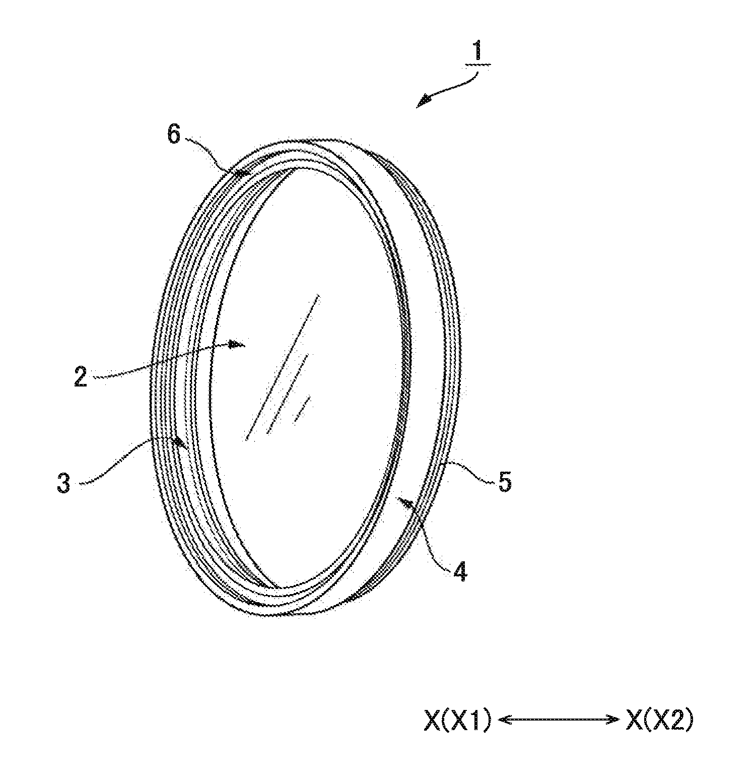
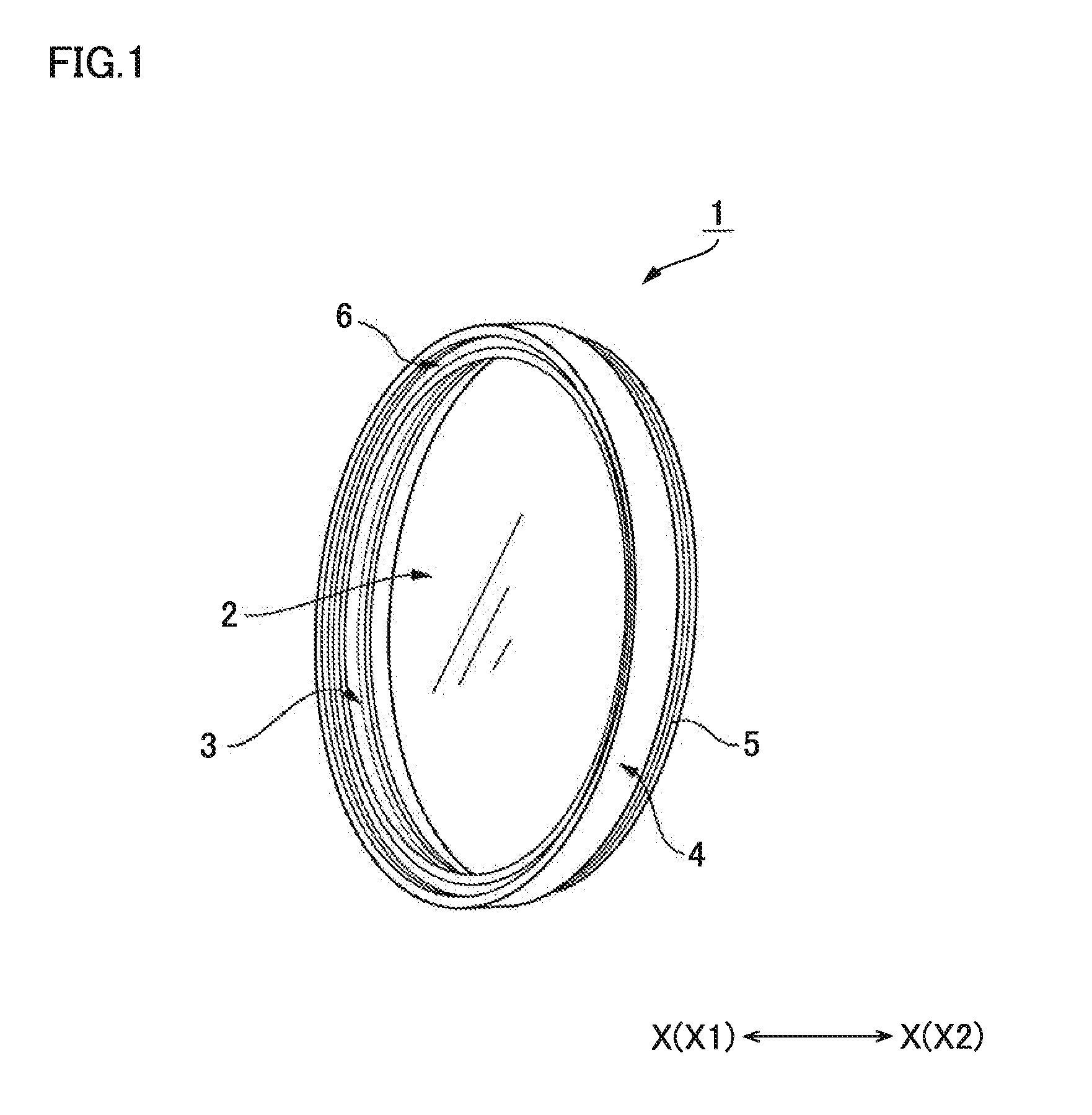
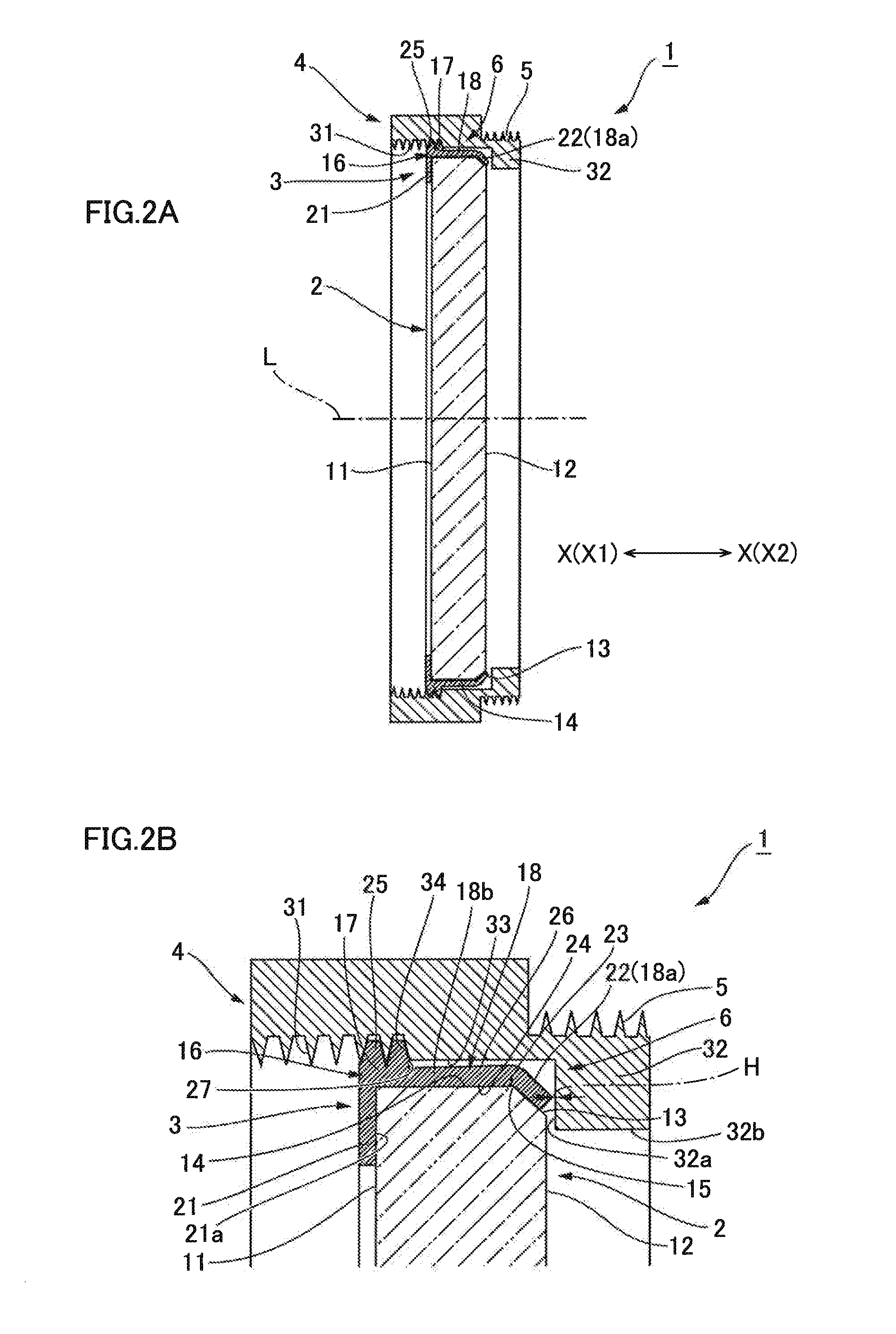
[0035]FIG. 1 is a perspective view of a camera filter unit to which the present invention is applied. FIG. 2A is a longitudinal sectional view schematically illustrating a camera filter unit 1 in FIG. 1. FIG. 2B is a partially enlarged sectional view in which the vicinity of the outer peripheral edge of an optical filter 2 is enlarged. FIGS. 3A and 3B are diagrams for explaining a manufacturing method of the camera filter unit 1. As illustrated in FIG. 1, the camera filter unit 1 according to the present invention has the optical filter 2, a filter holding ring 3 in which the optical filter 2 is fitted coaxially, and a filter frame 4 that holds the filter holding ring 3 coaxially from the outer peripheral side. The filter holding ring 3 and the filter frame 4 constitute a camera filter frame 6 that holds the optical filter 2. The filter holding ring 3 and the filter frame 4 are formed of a metal base such as aluminum and brass. In the present embodiment, the filter h...
second embodiment
[0069]FIG. 5 is a diagram illustrating a camera filter unit according to a second embodiment. In a camera filter unit 1A according to the present embodiment, the filter holding ring 3 includes adhesive injection holes 46 in the annular plate 18. An adhesive 47 is interposed between the filter holding ring 3 and the optical filter 2. Note that the other components are the same as those of the camera filter unit 1 according to the first embodiment illustrated in FIG. 2, are denoted by the same reference numerals, and description thereof will be omitted.
[0070]As illustrated in FIG. 5, the adhesive injection holes 46 penetrate the cylinder 18b of the annular plate 18 in the direction orthogonal to the axis L. Three adhesive injection holes 46 are disposed at equal angular intervals in the circumferential direction of the cylinder 18b. Each of the adhesive injection holes 46 includes a tapered inner peripheral surface the inner diameter dimension of which decreases from the outer periphe...
third embodiment
Modification of Third Embodiment
[0087]FIGS. 8A and 8B are diagrams illustrating a camera filter unit according to a modification of the third embodiment. Note that a camera filter unit 1C according to the present embodiment includes components corresponding to those of the camera filter unit 1B according to the second embodiment, and thus the same reference numerals are given to the corresponding components and description thereof will be omitted.
[0088]In a camera filter unit 1C according to the present embodiment, the optical filter 2 includes the tapered annular chamfered surface 13 that is continuous to the outer peripheral edge of the rear filter surface 12 and inclines to the outer peripheral side toward the front X1. To the outer peripheral end edge of the annular chamfered surface 13, the annular outer peripheral surface 14 is continuous, extending to the front X1. Between the annular chamfered surface 13 and the annular outer peripheral surface 14 is the corner 15. The optic...
PUM
 Abstract
Description
Claims
Application Information
 - R&D Engineer
- R&D Manager
- IP Professional
- Industry Leading Data Capabilities
- Powerful AI technology
- Patent DNA Extraction
Browse by: Latest US Patents, China's latest patents, Technical Efficacy Thesaurus, Application Domain, Technology Topic.
© 2024 PatSnap. All rights reserved.Legal|Privacy policy|Modern Slavery Act Transparency Statement|Sitemap