Passive fluid regulation system

a fluid regulation system and fluid technology, applied in the direction of service pipe system, functional valve type, valve operating means/releasing devices, etc., can solve the problems of substantial property damage or even loss of life, substantial fluid loss, and all-in-one leakage of toilets, faucets, showers, etc., to improve safety, reduce operational costs, and facilitate installation. the effect of safe and convenien

Active Publication Date: 2016-04-07
ACCURATE SITE DEV
View PDF23 Cites 8 Cited by
  • Summary
  • Abstract
  • Description
  • Claims
  • Application Information

AI Technical Summary

Benefits of technology

[0018]Yet another object of the present invention is to provide a fluid regulation system that can work in a variety of applications. A feature of the present invention is that the system can be adapted to regulate, among other things, water flow to bathroom fixtures, either individually or to the entire bathroom, and to regulate fuel flow to residential and commercial applications, such as kitchen appliances. An advantage of the present invention is that safety is improved in those applications, while operational costs are reduced.
[0019]Another object of the present invention is to provide a fluid regulation system that is passive in nature. A feature of the present invention is that a pressurized fluid is made accessible to a fixture in a room when a light switch in the same room is actuated. An advantage of the present invention is that when a user enters a room, he or she will naturally turn on the lights, which will initiate supply of pressurized fluid to the fixture. When the user exits the room, he or she will naturally turn off the lights, thereby shutting off flow of pressurized fluid to the fixture.
[0020]An additional object of the present invention is to provide a fluid regulation system that is easy and safe to install. A feature of the present invention is that the present invention is considered a low voltage Class 2 circuit, which operates at lower energy and improves fire safety. An advantage of the present invention is that the components are all Underwriters Laboratories (UL®) listed and readily available commercially. Another advantage of the present invention is that the components are relatively inexpensive compared to other fluid regulation devices.
[0021]Yet another object of the present invention is to provide a wireless fluid regulatio

Problems solved by technology

Failure (leakage, freeze damage) of these fluid lines at a minimum results in substantial fluid loss.
In worse case scenarios, substantial property damage or even loss of life occurs.
Toilets, faucets, showers, and other bathroom fixtures will all eventually leak.
Toilets in particular develop slow leaks as a result of a damaged flapper, mineral buildup that prevents proper sealing, or a leaky water inlet valve.
If leaks exist in the tank or inlet valve, or if the toilet begins to overflow, water continues to flow into the tank and eventually spills over onto the floor.
Thus, leaks can cause a toilet to constantly fill and to potentially spew water.
Even for a single residential toilet, such leaks can waste several thousands of gallons of water a year.
This can result in higher water bills or depleted well reserves.
Additionally, wasting water has environmental impacts, especially in drought-ridden areas.
These problems are further exacerbated in commercial or institutional settings where several toilets coul

Method used


Image

  • Passive fluid regulation system
  • Passive fluid regulation system
  • Passive fluid regulation system

Examples


Embodiment Construction

[0034]The foregoing summary, as well as the following detailed description of certain embodiments of the present invention, will be better understood when read in conjunction with the appended drawings.

[0035]As used herein, an element step recited in the singular and preceded with the word “a” or “an” should be understood as not excluding plural said elements or steps, unless such exclusion is explicitly stated. Furthermore, the references to “one embodiment” of the present invention are not intended to be interpreted as excluding the existence of additional embodiments that also incorporate the recited features. Moreover, unless explicitly stated to the contrary, embodiments “comprising” or “having” an element or a plurality of elements having a particular property may include additional such elements not having that property.

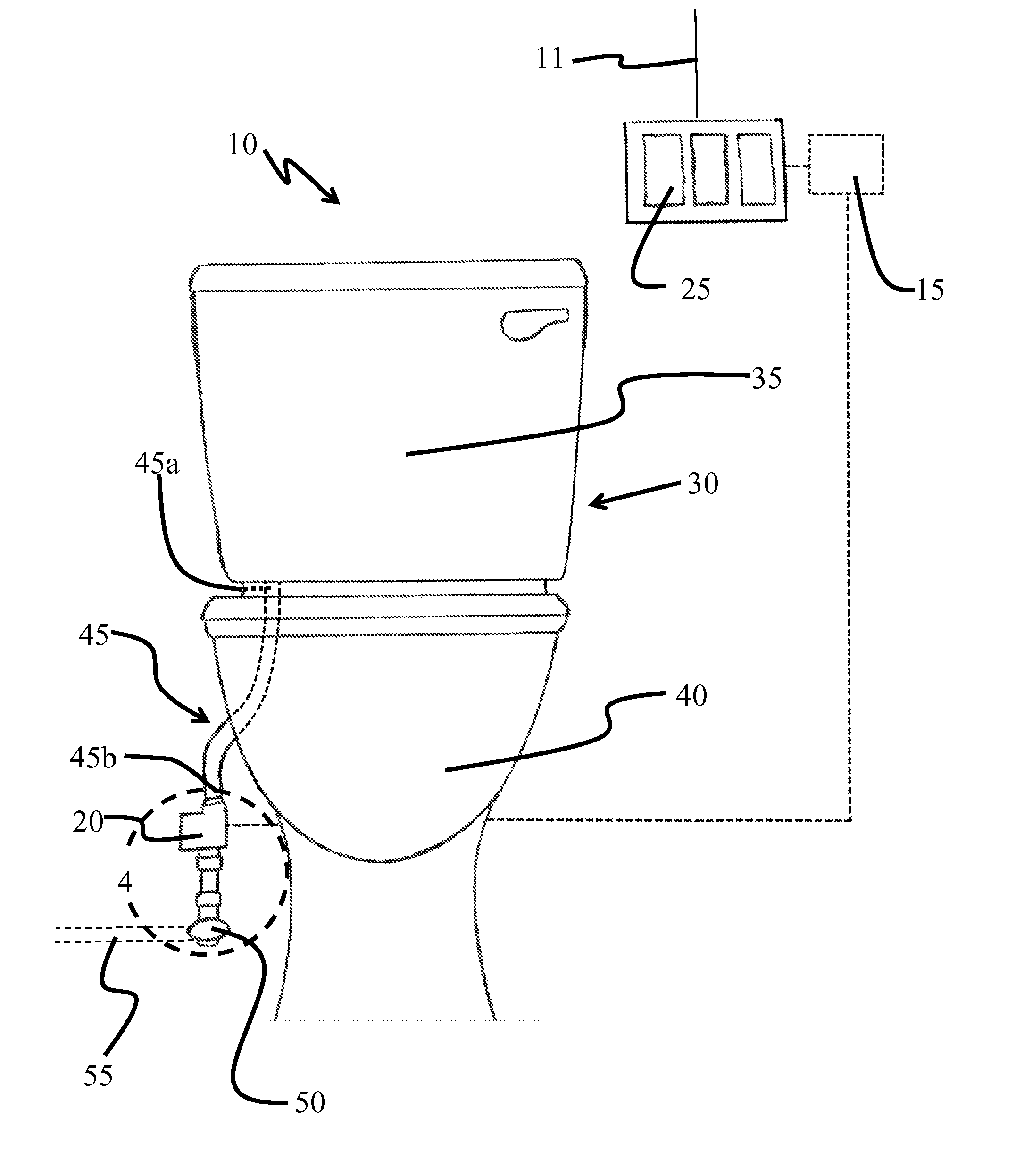
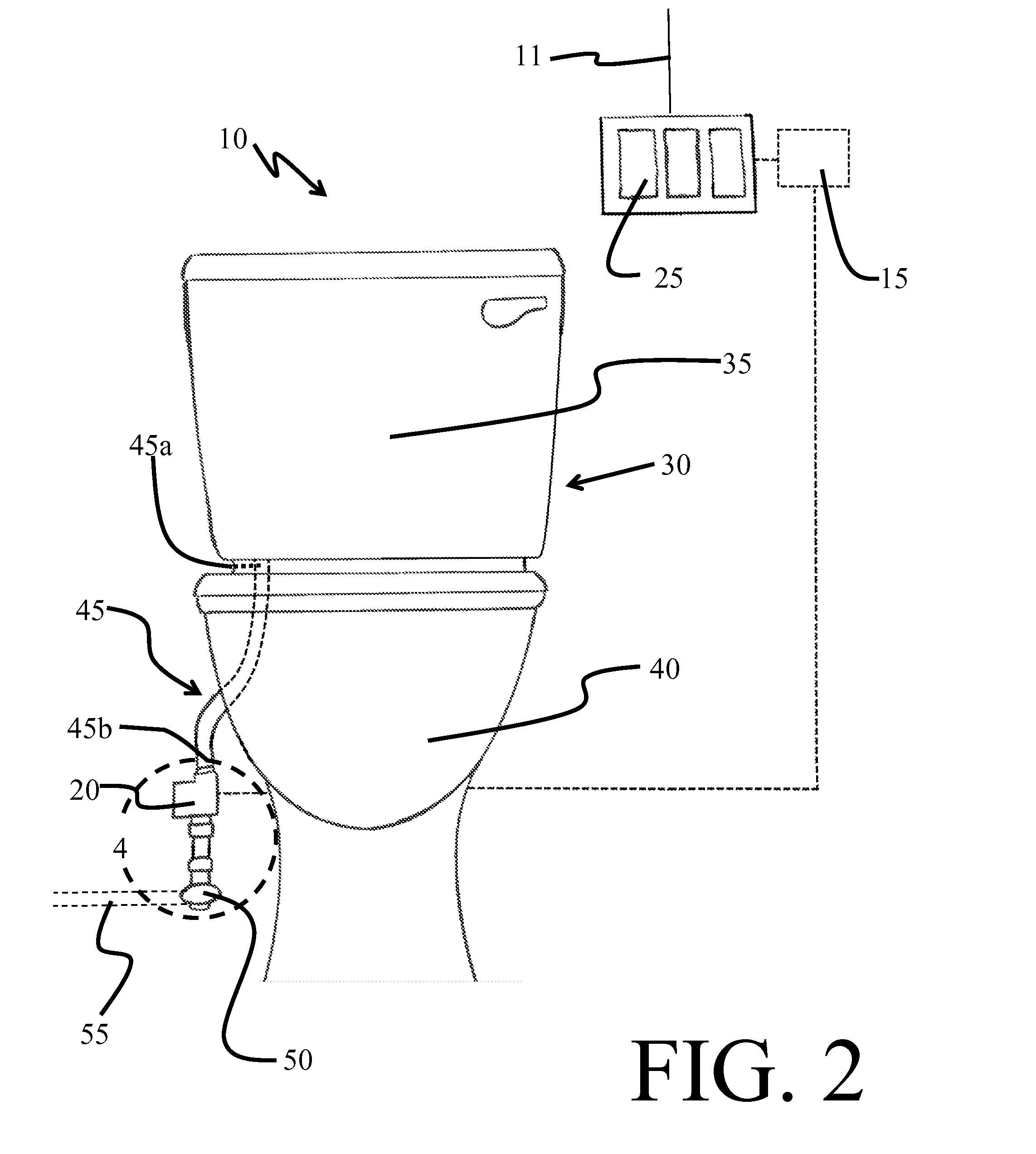
[0036]The present invention is directed to a passive fluid regulation system, designated as numeral 10 in FIG. 2. The system 10 is placed downstream and in fl...


PUM


Abstract

The present invention provides a system to regulate fluid flow having a light switch that controls a light, wherein the light switch is in electrical communication with a wireless transmitter; and at least one valve interposed on at least one fluid supply line wherein said at least one valve is normally closed, cutting off the flow of fluid in the at least one fluid supply line, wherein the at least one valve is in electrical communication with a wireless receiver such that when the light switch is activated the wireless transmitter signals the wireless receiver to open the valve, allowing flow of fluid in the fluid supply line. The present invention also provides another system using a photocell switch to actuate the valve.

Description

CROSS-REFERENCE TO RELATED APPLICATIONS[0001]This application claims the benefit of priority as a continuation-in-part to U.S. patent application Ser. No. 14 / 506,911, filed on Oct. 6, 2014, which is currently pending.BACKGROUND OF THE INVENTION[0002]1. Field of the Invention[0003]This invention is directed to a passive fluid regulation system, and more specifically this invention is related to fluid control to a fixture via operation of a light switch.[0004]2. Background of the Invention[0005]Many household and commercial devices are supplied with pressurized fluids for activities related to heating, cooling, cooking, and waste removal. Exemplary fluids include fuel products (oil, methane, propane), and cooking and waste removal agents (water and air).[0006]Water is the most ubiquitous of these agents. A single family residence contains multiple sill cocks, faucets, weather exposed conduits and valves servicing standard fixtures, such as sinks, toilets, and washers. Water outlets ar...

Claims


Application Information

Patent Timeline
IPC IPC(8): E03C1/05E03C1/02F16K37/00F16K31/06F16K5/06F16K31/04
CPCE03C1/057F16K5/06E03C1/02F16K37/0083F16K31/06F16K31/046E03B7/071Y02A20/15
Inventor GUIDISH, JEROME J.
Owner ACCURATE SITE DEV
Why Eureka
Try Eureka