
Filter circuit

Active Publication Date: 2016-04-07
YAZAKI CORP
View PDF0 Cites 2 Cited by
  • Summary
  • Abstract
  • Description
  • Claims
  • Application Information

AI Technical Summary

Benefits of technology

The present invention aims to provide a filter circuit that can effectively reduce noise in a specific frequency range even when a high DC voltage is applied. The circuit includes a capacitor connected between the input and ground terminals, which can help reduce noise. However, the capacitance of the capacitor may lower with time, leading to a decrease in the effectiveness of the filter. To address this, the circuit includes a resistance determination to compensate for the expected decrease in capacitance and ensure the filter's ability to reduce noise. The filter circuit also uses a ceramic filter for efficient and reliable operation, while being cost-effective.

Problems solved by technology

The actual voltage of each battery cell, however, is affected by complex fluctuations in current along with the charging and discharging, the intrusion of noise from outside, and others.
That is, when measuring the DC voltage of each battery cell is attempted, there is a possibility of the occurrence of a serious measurement error, by the influence of noise of AC or high frequencies.
In the RC filter unit in Japanese Patent Application Laid-open No. 2003-282158, however, because a capacitor is connected between the terminals of each of the battery cells, there is a possibility of not being able to remove the noise adequately.
In that case, however, the voltage applied between the terminals of the capacitor becomes high, and thus it is necessary to increase the withstand voltage of each capacitor.
In this case, it is further conceivable that, due to a DC bias voltage of the capacitor, the capability of the filter may be deteriorated and an adverse effect may appear in the measurement of voltage.
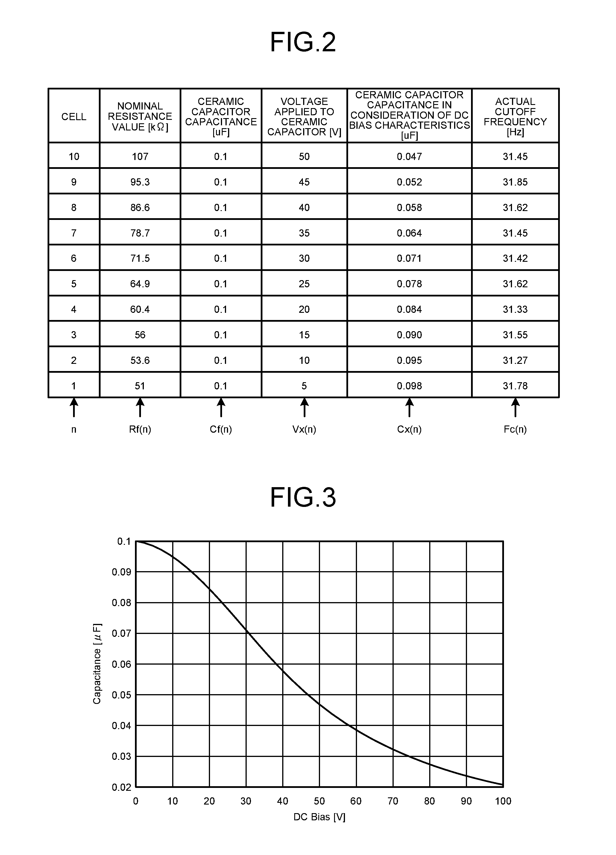
The ceramic capacitor, however, has a tendency of the capacitance to fluctuate depending on the applied DC bias voltage.
When the capacitance fluctuates, the cutoff frequency of the filter is varied, and thereby the noise in low frequencies may not be removed adequately.
Furthermore, when the cutoff frequency of the filter is conversely too low, the effect of the filter appears in also fast fluctuations in voltage of the battery cell itself other than the noise, and thus it is conceivable that the capability of monitoring the voltage may be deteriorated and that the capacitor may increase in size more than necessary.

Method used


Image

  • Filter circuit
  • Filter circuit
  • Filter circuit

Examples


Embodiment Construction

[0025]The following describes a specific exemplary embodiment concerning a filter circuit according to the present invention with reference to the accompanying drawings.

[0026]Configuration of Circuit

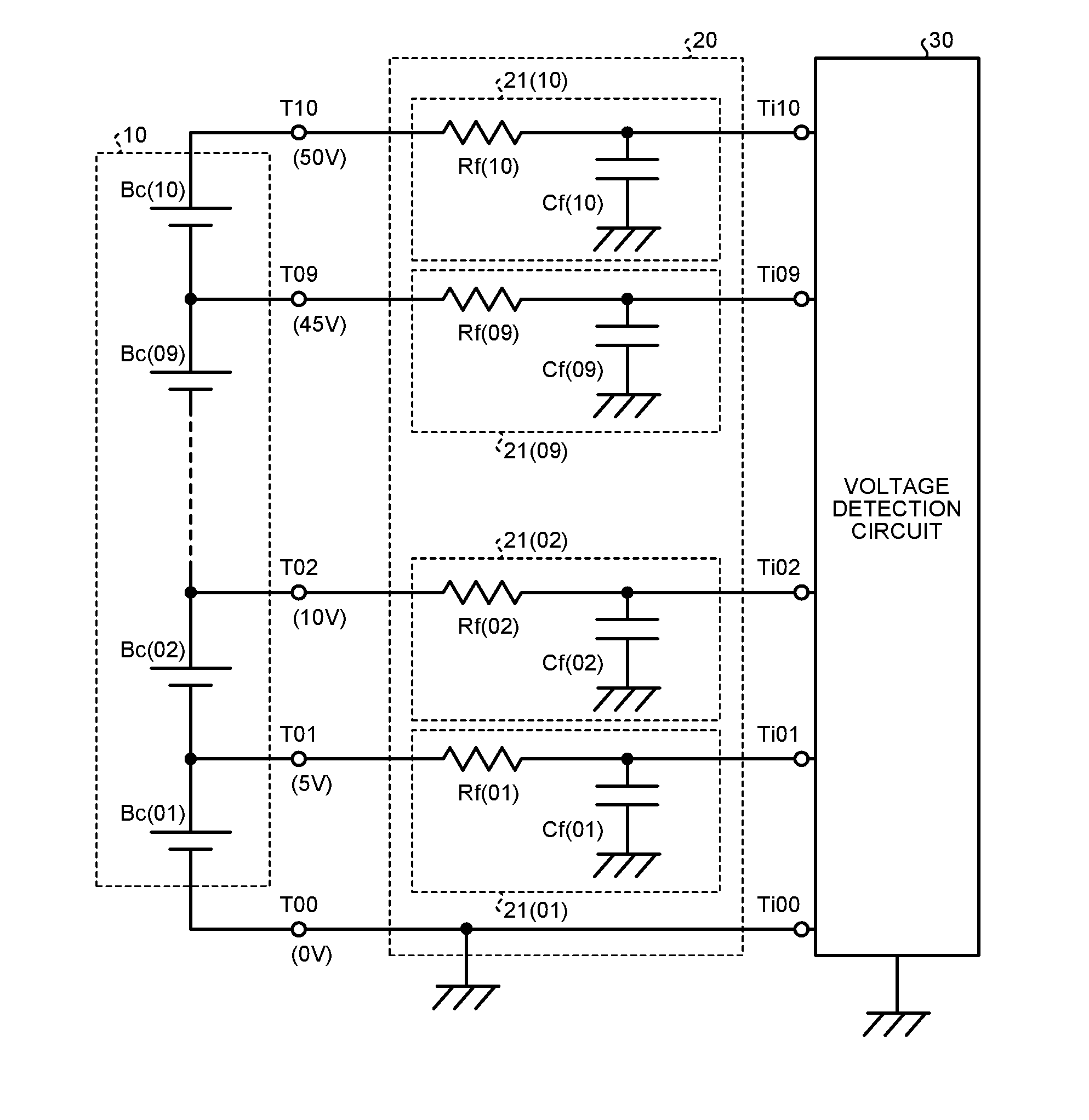
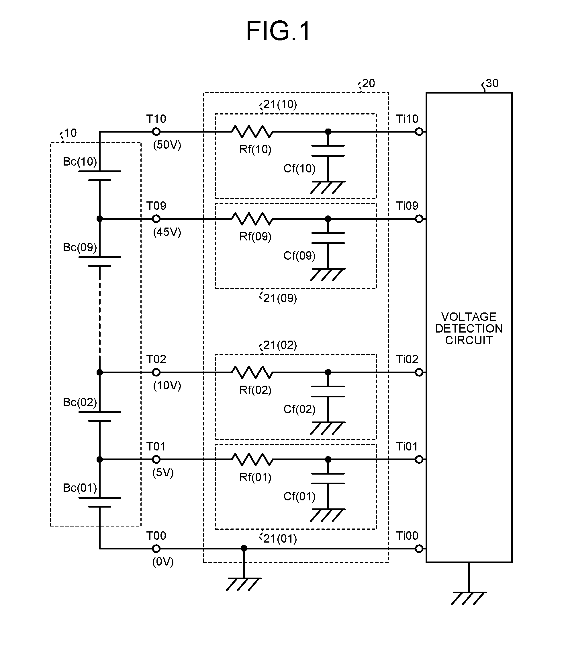
[0027]FIG. 1 illustrates an example of the configuration of an apparatus including a filter circuit 20 according to the embodiment.

[0028]The apparatus illustrated in FIG. 1 can be assumed to be used in a state of being installed as a power source in an electric vehicle and a hybrid vehicle, for example. That is, a battery pack circuit 10 illustrated in FIG. 1 is used as a supply source of the electrical power necessary to generate a driving force of the vehicle.

[0029]Consequently, in the configuration example in FIG. 1, the battery pack circuit 10 is configured with 10 pieces of battery cells Bc(01), Bc(02), . . . , Bc(09), and Bc(10) connected in series so as to be able to supply an adequately high voltage. Each of the battery cells Bc(01) to Bc(10) is configured with a secondary batter...


PUM


Abstract

By configuring low-pass filters each with a resistor and a capacitor, noise is removed. Based on a reference value of DC voltage that appears at output terminals of a battery pack circuit, a lowering portion of capacitance that arises in the respective capacitors is estimated in advance, and a compensation value is included in the resistance value of the respective resistors such that the cutoff frequencies of the low-pass filters are within an intended range. Even when a high voltage is handled, the variance in cutoff frequencies can be prevented from arising and the noise in an unnecessary frequency domain can be adequately reduced.

Description

CROSS-REFERENCE TO RELATED APPLICATION[0001]This application is a continuation application of International Application PCT / JP2014 / 065746, filed on Jun. 13, 2014, and designating the U.S., the entire contents of which are incorporated herein by reference.BACKGROUND OF THE INVENTION[0002]1. Field of the Invention[0003]The present invention relates to a filter circuit that is usable in an electric vehicle and a hybrid vehicle, for example.[0004]2. Description of the Related Art[0005]In an electric vehicle and a hybrid vehicle, as a power source that is usable for driving the vehicle, a secondary battery such as a lithium ion battery is used, for example. Furthermore, because the voltage is low with only a single battery, a battery pack circuit that is configured with a number of battery cells, for example, of eight or more being connected in series is used.[0006]When such a battery pack circuit is employed, whether each of the battery cells is operating properly along with operations ...

Claims


Application Information

Patent Timeline
IPC IPC(8): G01R31/36H01M10/42H01M10/48
CPCG01R31/3658H01M10/482H01M10/425H01M2010/4271G01R31/362H01M2220/20G01R31/3662G01R19/0053G01R19/16542B60L3/12B60L2240/547B60L58/21G01R31/396G01R31/3835Y02T10/70Y02E60/10G01R31/389
Inventor CHIYAJO, YUKISHIMIZU, HIDEHIKOWAKASUGI, YASUTAKA
Owner YAZAKI CORP
Learn More