Rotating electric machine and method of operating the same

a technology of rotating electric machines and rotating parts, which is applied in the direction of rotating parts of magnetic circuits, magnetic circuit shapes/forms/construction, transportation and packaging, etc., can solve the problem of low overall cooling efficiency and achieve efficient cooling and overall cooling efficiency improvement

Inactive Publication Date: 2016-04-07
MITSUBISHI ELECTRIC CORP
View PDF8 Cites 28 Cited by
  • Summary
  • Abstract
  • Description
  • Claims
  • Application Information

AI Technical Summary

Benefits of technology

[0007]The present invention has been made to solve the problem described above, and therefore has an object to provide a rotating electric machine having improved cooling efficiency as a whole by enabling a coolant to flow around a stator and around and through a rotor in parallel for both the stator and the rotor to allow the stator and the rotor to be cooled in parallel.
[0008]Further, the present invention has another object to provide a method of operating the rotating electric machine, which is capable of efficiently cooling each of the stator and the rotor by changing a flow-rate allocation of the coolant flowing to the stator side and that of the coolant flowing to the rotor side based on physical quantities of internal states of the rotating electric machine.
[0022]According to the rotary electric machine of one embodiment of the present invention, the stator and the rotor can be cooled in parallel by enabling the coolant to flow around the stator and around and through the rotor in parallel for both the stator and the rotor. As a result, the overall cooling efficiency can be improved.
[0023]Further, according to the method of operating the rotating electric machine of one embodiment of the present invention, the flow-rate allocation of the coolant flowing to the stator side and that of the coolant flowing to the rotor side are changed based on the physical quantities of the internal states of the rotating electric machine. As a result, a proper amount of the coolant is fed to each of the stator and the rotor. Hence, the stator and the rotor can be efficiently cooled, respectively.

Problems solved by technology

Thus, the above-mentioned rotating electric machines have a problem in that cooling efficiency as a whole is low.

Method used


Image

  • Rotating electric machine and method of operating the same
  • Rotating electric machine and method of operating the same
  • Rotating electric machine and method of operating the same

Examples


first embodiment

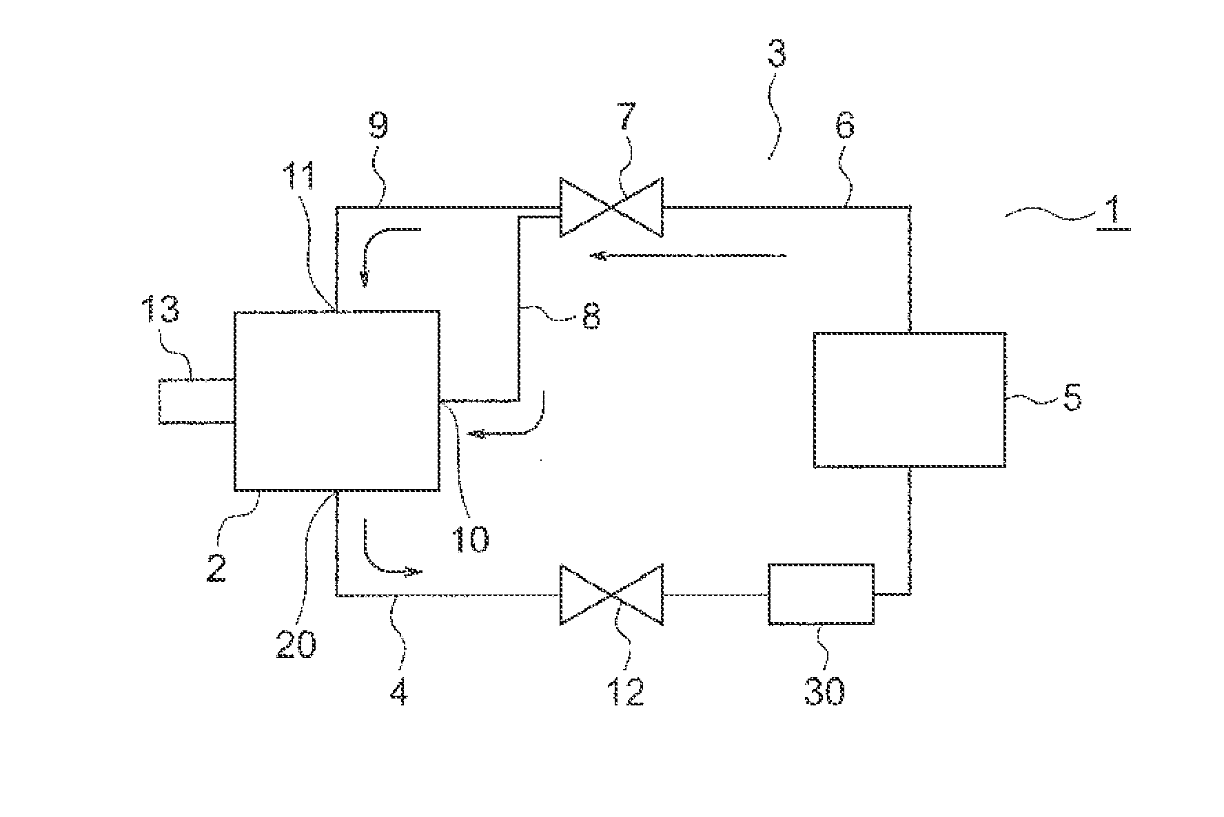
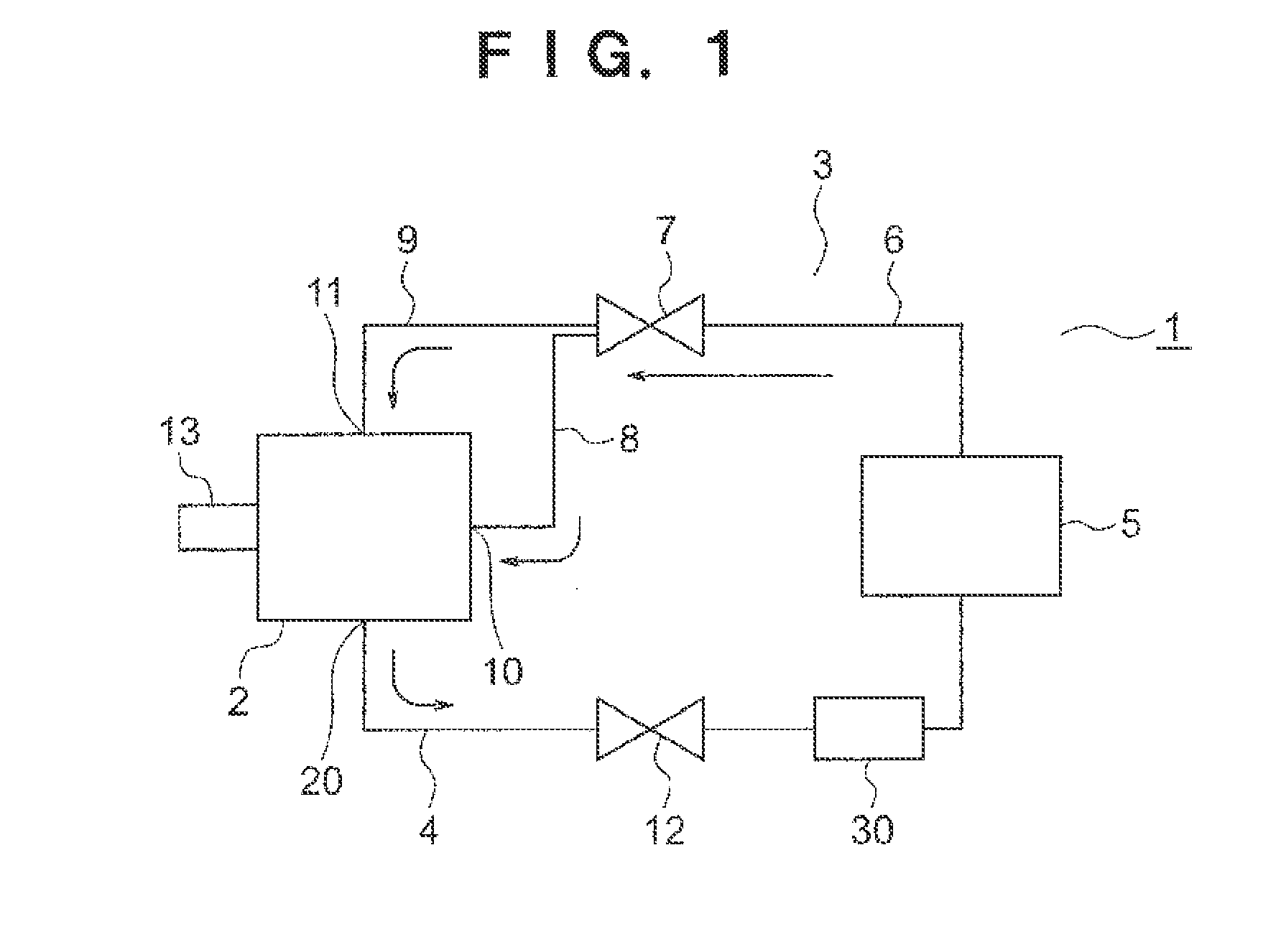
[0029]FIG. 1 is a coolant circuit diagram of an electric motor 1 which is a rotating electric machine according to a first embodiment of the present invention.

[0030]The electric motor 1, which is to be mounted in an automobile, includes an electric motor main body 2 which is a rotating electric machine main body, a pump 5, an outgoing pipe 3, and a return pipe 4. The electric motor main body 2 and the pump 5 are connected to each other through the outgoing pipe 3 and the return pipe 4.

[0031]The outgoing pipe 3 includes a pipe main body 6. The pipe main body 6 has one end portion connected to the pump 5 and another end portion to which a three-way valve 7 is mounted. On a downstream side of the three-way valve 7, a first outgoing pipe portion 8 and a second outgoing pipe portion 9 branch from the pipe main body 6. A distal end portion of the first outgoing pipe portion 8 is connected to a first coolant inflow port 10 of the electric motor main body 2. A distal end portion of the seco...

second embodiment

[0067]FIG. 4 is a coolant circuit diagram of an electric motor 1 according to a second embodiment of the present invention.

[0068]In the second embodiment, the outgoing pipe 3 includes a first outgoing pipe portion 8A and a second outgoing pipe portion 9A. The first outgoing pipe portion 8A has one end portion connected to the pump 5 and another end portion connected to the first coolant inflow port 10 of the electric motor main body 2. The second outgoing pipe portion 9A has one end portion connected to the pump 5 and another end portion connected to the second coolant inflow port 11 of the electric motor main body 2.

[0069]A first two-way valve 32 is mounted to a middle portion of the first outgoing pipe portion 8A, whereas a second two-way valve 33 is mounted to a middle portion of the second outgoing pipe portion 9A.

[0070]The remaining configuration is the same as that of the electric motor 1 according to the first embodiment.

[0071]In the electric motor 1 according to the first em...


PUM


Abstract

Provided is an electric motor having improved overall cooling efficiency by enabling a coolant to flow around a stator and around and through a rotor in parallel for the stator and the rotor to allow the stator and the rotor to be cooled in parallel. In the electric motor, after an automatic transmission fluid flowing into a first coolant inflow port (10) passes through a shaft internal flow path and rotor internal flow paths (27), the automatic transmission fluid passes through a coolant exhaust port (20) to flow out of a housing (18). After the automatic transmission fluid flowing into a second coolant inflow port (11) passes through a clearance (31) between the housing (18) and a stator (17) and around coil ends (29) of stator coils (16), the automatic transmission fluid passes through the coolant exhaust port (20) to flow out of the housing (18).

Description

BACKGROUND OF THE INVENTION[0001]1. Field of the Invention[0002]The present invention relates to a rotating electric machine to be cooled by a coolant flowing inside of the rotating electric machine, and to a method of operating the same.[0003]2. Description of the Related Art[0004]There is conventionally known a rotating electric machine in which a coolant supplied into a hollow shaft is scattered by rotation of the hollow shaft itself to cool coil ends of a stator (see, for example, Japanese Patent Application Laid-open No. 2013-115848).[0005]The following rotating electric machine is also known. The rotating electric machine includes a ring member provided on an outer circumference of a stator core and a case which houses the stator core and the ring member therein. A coolant is supplied between the ring member and the case so that the coolant is supplied to coil ends of a stator through holes formed through the ring member (see, for example, Japanese Patent Application Laid-open...

Claims


Application Information

Patent Timeline
Patent Type & Authority Applications(United States)
IPC IPC(8): H02K9/19
CPCH02K9/19H02K1/20H02K1/32B60L1/02B60L2240/421B60L2240/423B60L2240/425Y02T10/64
Inventor YOSHINORI, MANABUHORII, MASAKI
Owner MITSUBISHI ELECTRIC CORP
Why Eureka
Try Eureka