
Molded denture and method and apparatus of making same

a technology of dentures and dentures, applied in the direction of additive manufacturing processes, manufacturing tools, instruments, etc., can solve the problems of improper occlusion (upper and lower teeth engagement), high labor intensity in the manufacture of dental prostheses, and high labor intensity in the manufacturing process

Inactive Publication Date: 2016-04-14
GLOBAL DENTAL SCI
View PDF3 Cites 38 Cited by
  • Summary
  • Abstract
  • Description
  • Claims
  • Application Information

AI Technical Summary

Benefits of technology

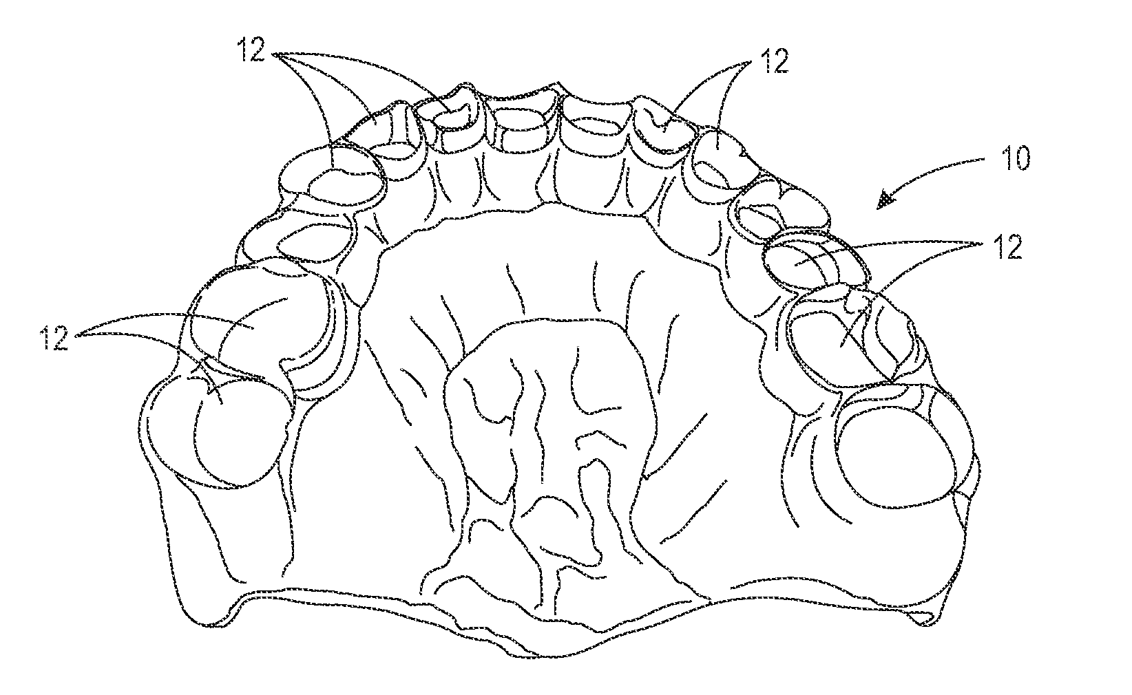
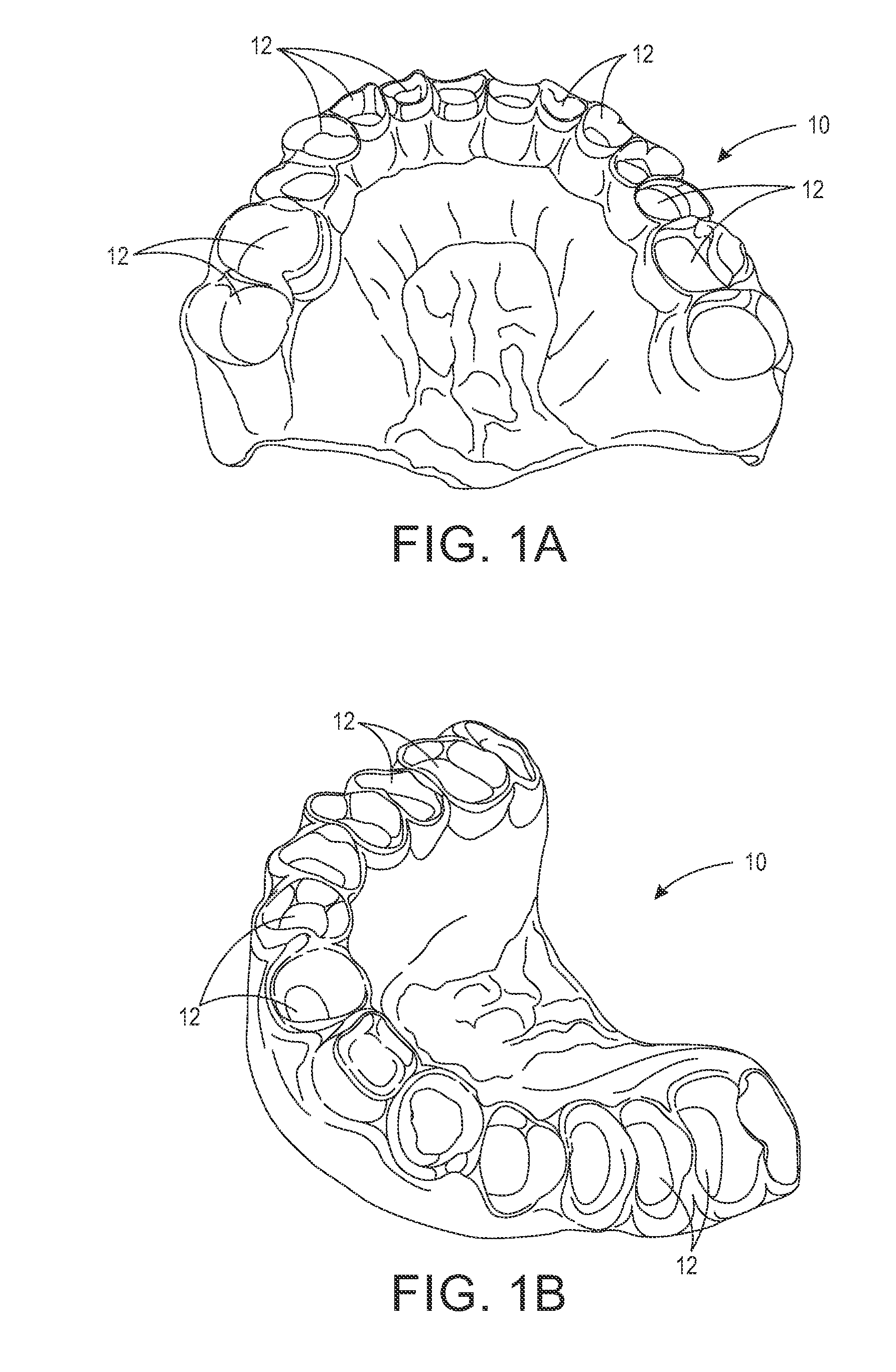
The present disclosure provides a solution for fabricating dentures at a low cost with minimal manual labor. By using a method and apparatus of printing dentures using 3D printing technology, the requirement for skilled manual labor is virtually eliminated, and errors during fabrication are minimized. A dental professional can create any shape and color of teeth to match the patient's needs, and a digital photo of the patient's face can be displayed to increase the likelihood of patient acceptance. The need for a dental lab to maintain a large stock of denture teeth is also eliminated, resulting in significant cost savings. The artificial teeth are chemically bonded to the denture base, reducing the likelihood of the teeth becoming loose or falling prey to bacterial growth. Overall, the present method and apparatus provide a more natural-looking and functional denture.

Problems solved by technology

Heretofore, the manufacturing of dental prostheses has been a highly labor intensive process requiring multiple fittings to a patient in need of them, and many steps that must be performed at the hands of skilled artisans.
It can be seen that in the above highly labor-intensive process, each of these steps introduces a potential for a processing error.
Even the slightest error, such as the investment being too cool, or the powder / water ratio of the investment being incorrect, may cause the crown to fit too tightly in the patient's mouth, resulting in improper occlusion (upper and lower teeth engagement).
The crown may thus have to be scrapped or reworked through at least one iteration of additional process steps at considerable cost to the patient, dentist, and / or manufacturing lab.
For example, subtle irregularities often found in anterior (front) teeth are difficult to replicate using CAD / CAM processes.
Manual methods of making anterior fixed prosthetics enable unlimited aesthetic options, only limited by the creativity of the artisan (dental laboratory technician).
Some CAD / CAM techniques involve the use of milling a monolithic block of ceramic that does not deliver optimal aesthetics (example: too opaque), especially for anterior applications.
However, this manual step may defeat the primary benefit of CAD / CAM: precise dimensional accuracy.
However, this system generates only a CAD replica in plastic (made by a 3D printer), which requires subsequent extensive processing to obtain a metal partial denture framework.
Hence there are still many error-prone steps after the CAD replica is made that can result in a poorly-fitting partial denture framework.
However, the materials available to use in three-dimensional printers are neither as dense nor cross-linked like a normal plastic artificial tooth.
Hence a problem remains with the resulting dentures because the denture teeth that are made with available 3D printing plastic materials are not sufficiently wear-resistant.
A problem with this approach is that most of the teeth must be adjusted to some extent to fit within the space required in order for the denture to properly occlude with the opposing arch of the opposing denture or the patients existing opposing teeth.
Manual labor is required for the adjustment of teeth; therefore, the potential for errors is introduced into the manufacturing process.
Another problem with this method is that artificial teeth are not consistently sized.
Over the course of use, material from the wall of the mold wears away, resulting in a mold cavity increasing in size.
Additionally, molds contain multiple cavities, and the wear is not necessarily uniform.
Thus the combination of wear with time and non-uniform wear of a mold results in the production of teeth that vary dimensionally within any given tooth size that is intended to be produced using the mold.
There is thus a problem in that the dimensional variation of artificial teeth is significant with respect to the dimensions of the sockets formed by the milling machine in which the teeth are to be fitted.
However, this practice is undesirable.
Additional labor is required for this step, which is costly and which is likely a manual process which can introduce potential errors to the denture fabrication.
The risk of denture tooth “pop-outs” (debonding from the denture base) is more likely because the volume of bonding material is quite small relative to the conventional method of bonding denture teeth, and the bonding surface may be restricted to the circumference of the denture tooth which interfaces with the denture base (and limited bonding of the area of the tooth that opposes the occlusal surface because this area has been adjusted to rest on the “floor” of the socket).
In addition, like the conventional approach, the patient will not see the final configuration of the denture until the delivery appointment, at which time the patient may reject the denture based on aesthetics.
The step to provide diatoric holes is yet another processing step that increases cost and introduces the potential for further errors, such as artificial tooth fracture.
However, it is not suitable for long-term dentures because the artificial teeth made in this manner look unaesthetic.
This process is not compatible with the above overall denture fabrication process in which the full set of teeth are milled from a single piece of plastic and bonded to the milled denture base.
One aspect of this technique is that the milling steps require significant time because the geometry to be milled is intricate and tolerances must be held to tight standards.
In addition, many lower cost desktop mills do not have the speed or reach to cut-away the unneeded material efficiently.
This significantly reduces the likelihood of the artificial teeth detaching from the denture base (referred as a “pop-out”), and the formation of dark demarcation lines around the junction of the artificial teeth and artificial gingiva due to bacterial growth.
(The latter problem is often found in dentures made with porcelain artificial teeth because there is no chemical bond between the denture base and the teeth.)

Method used


Image

  • Molded denture and method and apparatus of making same
  • Molded denture and method and apparatus of making same
  • Molded denture and method and apparatus of making same

Examples


Embodiment Construction

[0074]The present invention will be described in connection with certain preferred embodiments. However, it is to be understood that there is no intent to limit the invention to the embodiments described. On the contrary, the intent is to cover all alternatives, modifications, and equivalents as may be included within the spirit and scope of the invention as defined by the appended claims.

[0075]For a general understanding of the present invention, reference is made to the drawings. In the drawings, like reference numerals have been used throughout to designate identical elements. The drawings are to be considered exemplary, and are for purposes of illustration only. The dimensions, positions, order and relative sizes reflected in the drawings attached hereto may vary.

[0076]It is also to be understood that any connection references used herein (e.g., attached, coupled, connected, joined) are to be construed broadly and may include intermediate elements and / or materials between at lea...


PUM

PropertyMeasurementUnit
shrinkaaaaaaaaaa
thicknessaaaaaaaaaa
shapeaaaaaaaaaa

Abstract

A method for making a denture comprising creating three-dimensional models of top denture base, bottom denture base, and denture tooth molds; fabricating the molds by an additive manufacturing process; joining the bottom denture base mold to the top denture base mold to form a denture base mold cavity; injecting fluid synthetic denture base material into the mold cavity and curing the material to form the denture base; removing the bottom denture base mold from the top denture base mold, while leaving the denture base in the top denture base mold; joining the denture tooth mold to the top denture base mold to form a mold cavity defining the shape of denture teeth; and injecting fluid synthetic denture tooth material into the denture teeth mold cavity and curing the material to form the denture teeth joined to the denture base. An apparatus for making the denture is also disclosed.

Description

CROSS-REFERENCE TO RELATED PATENT APPLICATIONS[0001]This application claims priority from U.S. Provisional Patent Application No. 62 / 062,936, filed Oct. 12, 2014; and further claims priority from U.S. Provisional Patent Application No. 62 / 093,728, filed Dec. 18, 2014. This application is also related to U.S. patent application Ser. No. 14 / 088,404, filed Nov. 24, 2013; U.S. patent application Ser. No. 14 / 180,260, filed Feb. 13, 2014; U.S. patent application Ser. No. 14 / 210,482, filed Mar. 14, 2014; U.S. patent application Ser. No. 14 / 212,532, filed Mar. 14, 2014; U.S. patent application Ser. No. 14 / 212,645, filed Mar. 14, 2014; and U.S. patent application Ser. No. 13 / 571,468, filed Aug. 10, 2012, and issued as U.S. Pat. No. 8,641,938 on Feb. 4, 2014. The disclosures of all of these United States patent applications are incorporated herein by reference.BACKGROUND[0002]1. Technical Field[0003]Dental prostheses and apparatus and methods of manufacturing them. In particular, computer-imp...

Claims


Application Information

Patent Timeline
Patent Type & Authority Applications(United States)
IPC IPC(8): A61C13/00A61C13/34
CPCA61C13/0006A61C13/34B33Y99/00B33Y10/00B33Y80/00A61C13/0004A61C13/081B29C64/106B29C64/118G16H20/40
Inventor HOWE, DEVON O.
Owner GLOBAL DENTAL SCI
Learn More