This helps you quickly interpret patents by identifying the three key elements:
Problems solved by technology
Method used
Benefits of technology
[0007]An embodiment provides a battery state estimation apparatus which can e
Problems solved by technology
Hence, according to the above technique, the amount of data, which can be used for calculation, becomes smaller in a temperature region of 0°
Method used
Image
Click on the blue label to locate the original text in one second.
Reading with bidirectional positioning of images and text.
Examples
first embodiment
[0028]Hereinafter, a battery state estimation apparatus according to the first embodiment is described with reference to the drawings. In the present embodiment, the apparatus is applied to, for example, a vehicle including a rotating electrical machine (motor generator) serving as an in-vehicle traction unit, or a vehicle utilizing an in-vehicle auxiliary unit battery for, for example, an idling stop system.
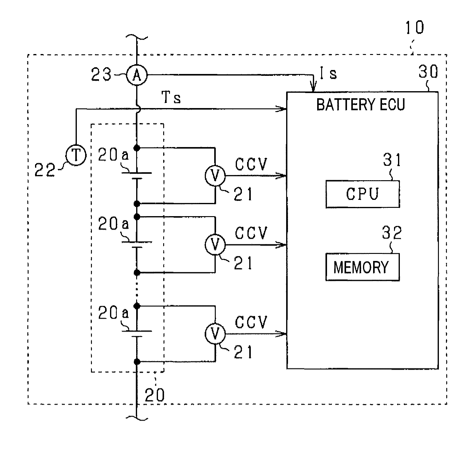
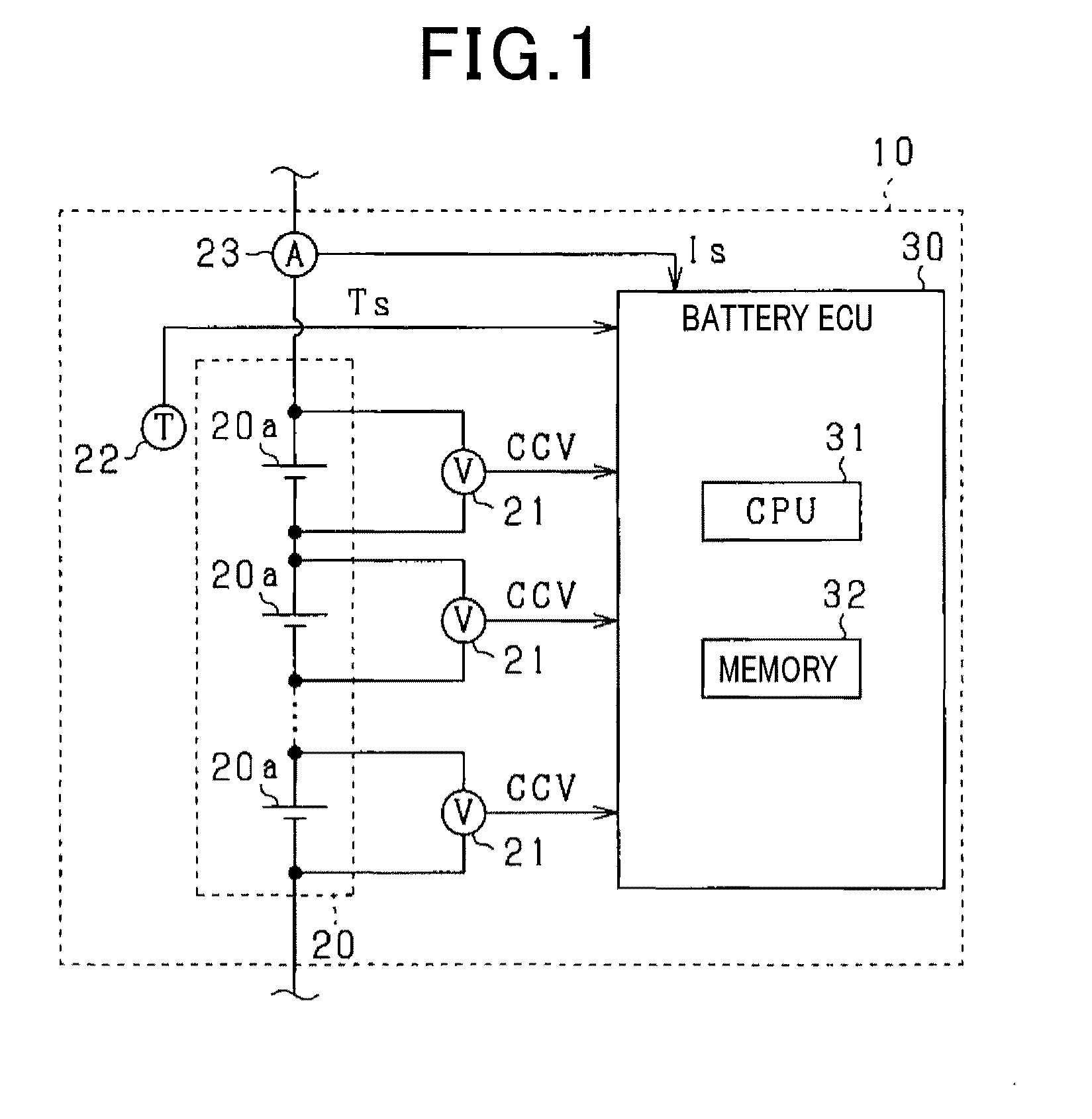
[0029]As shown in FIG. 1, a battery pack 10 includes an assembled battery 20 and a battery ECU (electronic control unit) 30. The assembled battery 20 is configured by a series connection of a plurality of battery cells 20a and supplies or receives electric power to or from a motor generator or the like, which is not shown. The battery cells 20a are secondary batteries. In the present embodiment, lithium-ion secondary batteries are used.
[0030]The battery pack 10 includes voltage sensors 21, a temperature sensor 22, and a current sensor 23. The voltage sensors 21 are voltage detec...
second embodiment
[0112]Hereinafter, the second embodiment is described focusing on the differences from the first embodiment with reference to the drawings. In the present embodiment, the process performed by the battery ECU 30 is modified.
[0113]The process performed by the battery ECU 30 is described with reference to FIG. 16. Note that, in FIG. 16, the same processes as those shown in FIG. 2 are denoted by the same reference numerals for the sake of convenience.
[0114]The battery ECU 30 includes the battery parameter calculation section 34, the voltage estimation section 35 for a diffusion region, a voltage estimation section 38 for a DC resistance section, an OCV calculation section 39, an SOC conversion section 40, an SOC correction amount calculation section 41, and an SOC estimation section 42.
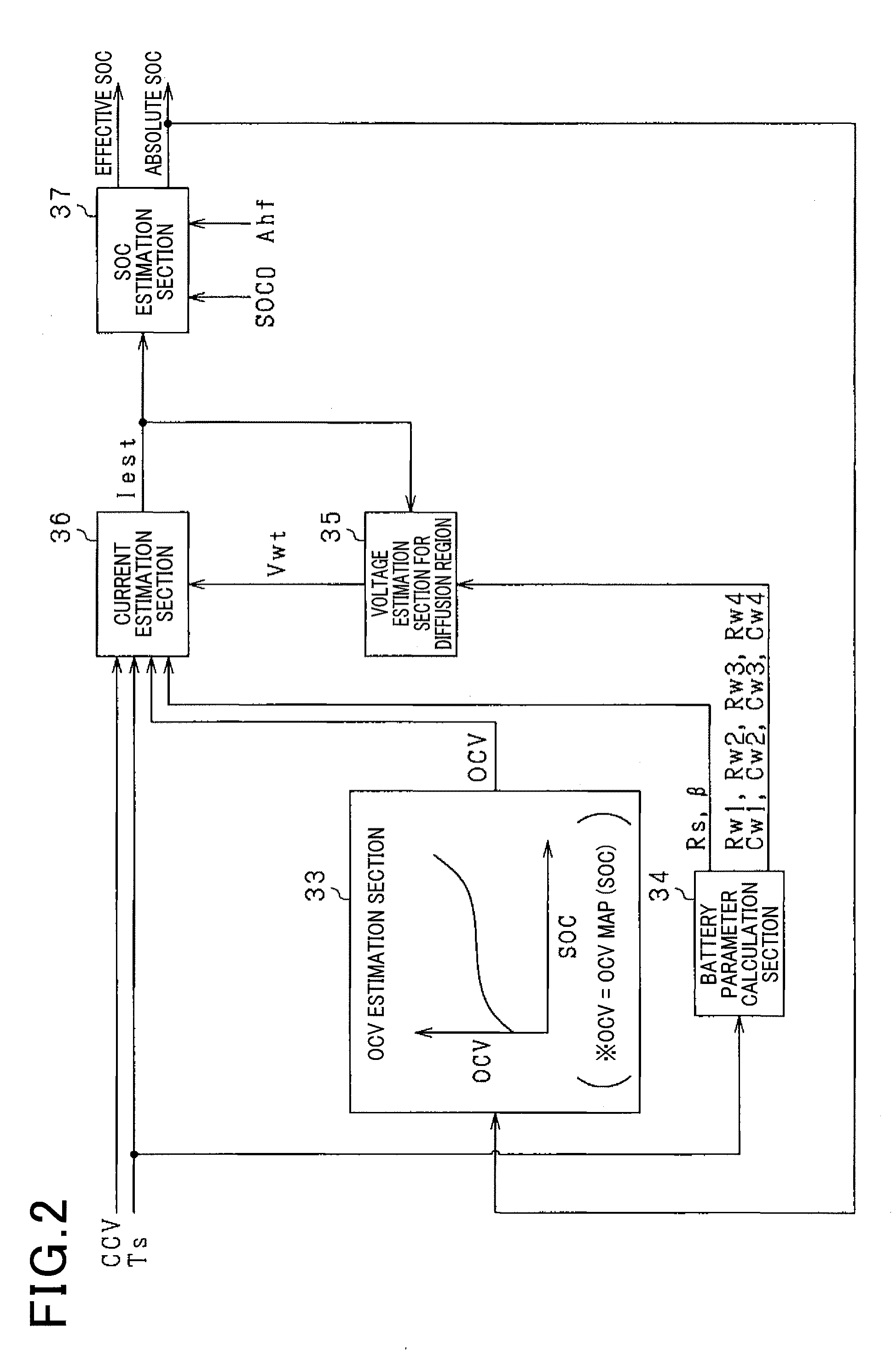
[0115]The voltage estimation section 35 calculates the diffusion resistance potential difference Vwt based on the parameters Rw1, Rw2, Rw3, Rw4, Cw1, Cw2, Cw3, Cw4 calculated by the battery parameter calc...
PUM
Abstract
A battery state estimation apparatus estimates a state of a secondary battery based on a battery model thereof. The battery model includes a DC resistance model, a reaction resistance model, and a diffusion resistance model. The apparatus includes a DC information storage section which stores information on the DC resistance related to temperature of the secondary battery, a reaction information storage section which stores information on the reaction resistance parameter related to the temperature, a diffusion information storage section which stores information on each of the first and second parameters related to the temperature, and a state estimation section which calculates the DC resistance, the reaction resistance parameter, and the first and second parameters from the stored information, by using the temperature as input, and estimates the state of the secondary battery based on the DC resistance, reaction resistance parameter, and first and second parameters.
Description
CROSS-REFERENCE TO RELATED APPLICATION[0001]This application is based on and claims the benefit of priority from earlier Japanese Patent Applications No. 2014-208263 filed Oct. 9 2014 and No. 2015-181048 filed Sep. 14 2015, the descriptions of which are incorporated herein by reference.BACKGROUND[0002]1. Technical Field[0003]The present invention relates to a battery state estimation apparatus which estimates a state of a secondary battery based on a battery model of the secondary battery.[0004]2. Related Art[0005]As described in JP-A-2012-159414, this type of apparatus is known which estimates a battery state including a nonlinear domain of current-voltage characteristics of a secondary battery based on a battery model (hereinafter, referred to as a 1RC equivalent circuit model) configured by a DC resistance and an RC equivalent circuit. Specifically, since the time constant is small, electrolyte resistance and both charge-transfer resistance and electric double capacitance are sim...
Claims
Application Information
Patent Timeline
Application Date:The date an application was filed.
Publication Date:The date a patent or application was officially published.
First Publication Date:The earliest publication date of a patent with the same application number.
Issue Date:Publication date of the patent grant document.
PCT Entry Date:The Entry date of PCT National Phase.
Estimated Expiry Date:The statutory expiry date of a patent right according to the Patent Law, and it is the longest term of protection that the patent right can achieve without the termination of the patent right due to other reasons(Term extension factor has been taken into account ).
Invalid Date:Actual expiry date is based on effective date or publication date of legal transaction data of invalid patent.