Liquid crystal display device and manufacturing method thereof

a liquid crystal display and liquid crystal technology, applied in the direction of optics, solid-state devices, instruments, etc., can solve the problems of excessive optical anisotropy in the alignment film itself, problems in the future to cope with products, etc., to achieve high liquid crystal alignment regulating force, low optical anisotropy, and wide viewing angle characteristics

Inactive Publication Date: 2016-04-14
JAPAN DISPLAY INC
View PDF5 Cites 10 Cited by
  • Summary
  • Abstract
  • Description
  • Claims
  • Application Information

AI Technical Summary

Benefits of technology

[0045]According to an aspect of the present invention, it is possible to provide a high-quality liquid crystal display device that achieves both of high liquid crystal alignment regulating force and low optical anisotropy, and has wide viewing angle characteristics, high display contrast, excellent stability, and less afterglow.

Problems solved by technology

However, ultraviolet rays also work in the inside of the film, for which a long-term structural stability is necessary, and the ultraviolet rays optically degrade the inside of the film, and at the same time, optical anisotropy is excessively formed in the alignment film itself.
Thus, the ultraviolet rays affect the viewing angle characteristics and contrast of the liquid crystal display device, leading to problems to cope with products in future.

Method used


Image

  • Liquid crystal display device and manufacturing method thereof
  • Liquid crystal display device and manufacturing method thereof
  • Liquid crystal display device and manufacturing method thereof

Examples


first embodiment

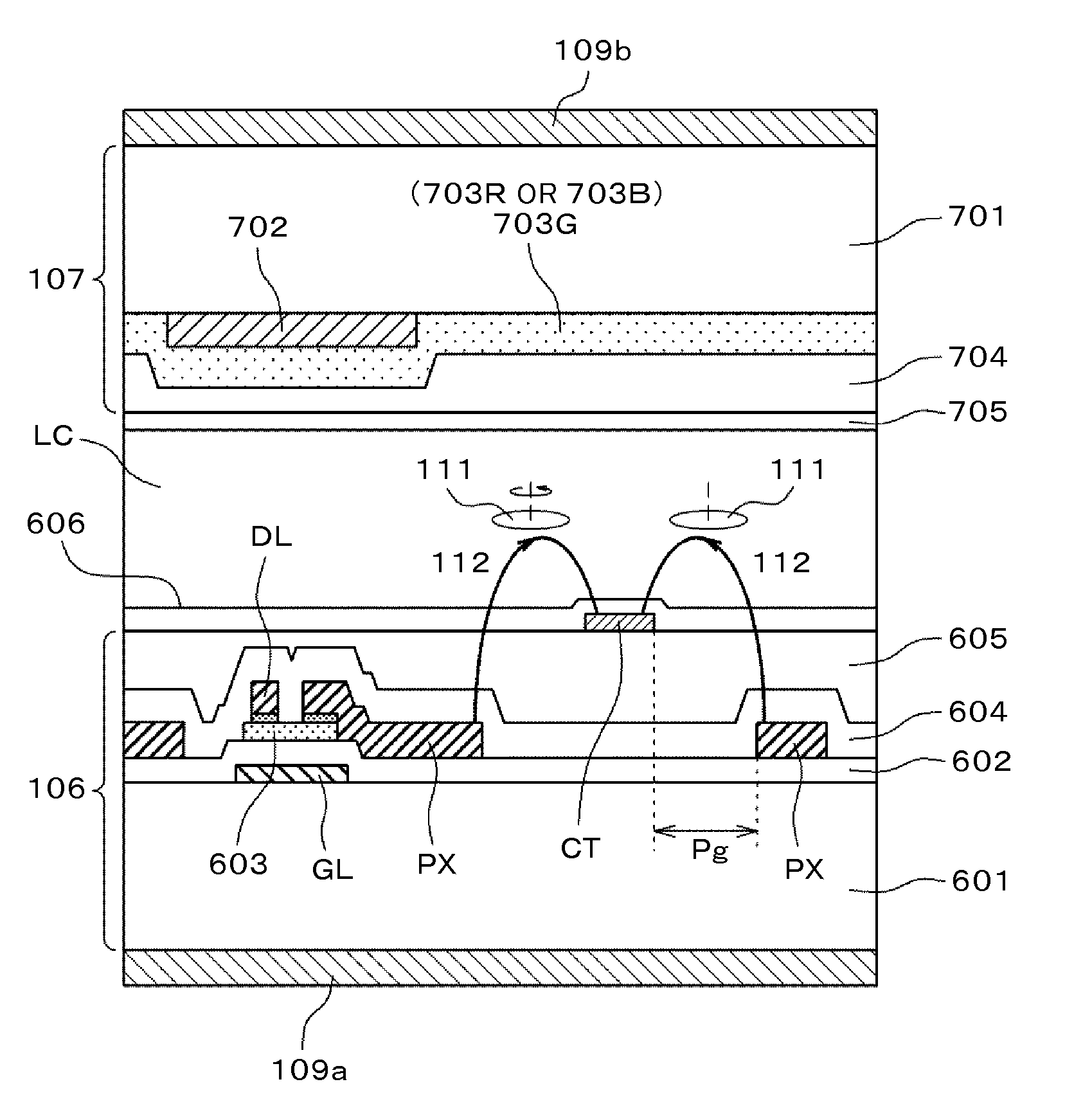
[0136]First, a result of preparing a liquid crystal display device will be described with reference to the drawings and tables, the liquid crystal display device including: a TFT substrate having a pixel electrode and a TFT and formed with an alignment film on a pixel; a counter substrate disposed opposite to the TFT substrate and formed with an alignment film on a topmost surface on the TFT substrate side; and a liquid crystal sandwiched between the alignment film of the TFT substrate and the alignment film of the counter substrate. In the liquid crystal display device, the alignment film is a material that is enabled to provide liquid crystal alignment regulating force by applying polarized light. The topmost surface layer of the photo-alignment film has liquid crystal alignment regulating force, and the photo-alignment film has little optical anisotropy.

[0137]Three types of substrates were used in which fused silica and no alkaline glass (AN-100 manufactured by Asahi Glass Co., L...

second embodiment

[0147]Next, a result confirming that such a film is obtained that the liquid crystal alignment regulating force is high and the optical anisotropy of the entire film is small as well as the performance of the liquid crystal display device is improved under different preparation conditions will be described with reference to the drawing and a table.

[0148]The same material as in the first embodiment was used for an alignment film material, alignment films were coated, imidized, and burned under the similar preparation conditions, and the alignment process or heat treatment was performed using the same polarized ultraviolet light source. Points different from the first embodiment are in that for the UV postprocess, these thin films were immersed in a hydrogen peroxide solution (3%) for one minute and subjected to pure water shower cleaning. A substrate for physical properties was only a glass substrate, and liquid crystal display devices were prepared also under the same conditions.

[01...

third embodiment

[0151]Next, a result confirming that such a film is obtained that the liquid crystal alignment regulating force is high and the optical anisotropy of the entire film is small as well as the performance of the liquid crystal display device is improved under different preparation conditions will be described with reference to the drawing and a table.

[0152]The same material in the first embodiment was used for an alignment film material, alignment films were coated, imidized, and burned under the similar preparation conditions, and the alignment process or heat treatment was performed using the same polarized ultraviolet light source. Points different from the first embodiment are in that for UV postprocess, these thin films were immersed in a hypochlorous acid solution (20 ppm) for 30 seconds and subjected to pure water shower cleaning. A substrate for physical properties was only a glass substrate, and liquid crystal display devices were prepared also under the same conditions.

[0153]...


PUM

PropertyMeasurementUnit
sizeaaaaaaaaaa
temperatureaaaaaaaaaa

Abstract

There is provided a high-quality liquid crystal display device that improves viewing angle characteristics and display contrast in low afterglow. A liquid crystal display device includes: a TFT substrate having a pixel electrode and a TFT and formed with an alignment film on a pixel; a counter substrate disposed opposite to the TFT substrate and formed with an alignment film on a topmost surface on the TFT substrate side; and a liquid crystal sandwiched between the alignment film of the TFT substrate and the alignment film of the counter substrate. The alignment film is a material that is enabled to provide liquid crystal alignment regulating force by applying polarized light. The topmost surface layer of the photo-alignment film has liquid crystal alignment regulating force, and the photo-alignment film has little optical anisotropy.

Description

CLAIM OF PRIORITY[0001]The present application claims priority from Japanese Patent Application JP 2014-207246 filed on Oct. 8, 2014, the content of which is hereby incorporated by reference into this application.FIELD OF THE INVENTION[0002]The present invention relates to a high-quality liquid crystal display device that improves viewing angle characteristics and display contrast and a manufacturing method thereof.BACKGROUND OF THE INVENTION[0003]Since liquid crystal display devices have merits such as high display quality, reduced thickness, reduced weight, and low power consumption, the use applications of the devices are expanding, and the devices are used for various use applications including mobile device monitors such as a mobile telephone monitor, digital still camera monitor, personal computer monitor, monitor intended for printing and design, medical monitor, and liquid crystal television. In association with the expansion of these use applications, it is demanded to furt...

Claims


Application Information

Patent Timeline
Patent Type & Authority Applications(United States)
IPC IPC(8): G02F1/1337H01L27/12G02F1/1368
CPCG02F1/133788H01L27/1262G02F1/133711G02F1/1368G02F1/133723G02F1/13378
Inventor IMANISHI, YASUO
Owner JAPAN DISPLAY INC
Why Eureka
Try Eureka