Fan motor driving means, driving method, and cooling device and electronic equipment using the same

Active Publication Date: 2016-04-21
ROHM CO LTD
View PDF2 Cites 9 Cited by
  • Summary
  • Abstract
  • Description
  • Claims
  • Application Information

AI Technical Summary

Benefits of technology

[0041]According to one aspect of the present invention, it is feasible

Problems solved by technology

Regarding the problems discussed in the Background, to sufficiently inhibit the voltage jump of the voltage, a high-performance Zener diode 108 or a high-volume smoothing capacitor 110 must be used, thereby causing the increase in the cost.
In the case where

Method used


Image

  • Fan motor driving means, driving method, and cooling device and electronic equipment using the same
  • Fan motor driving means, driving method, and cooling device and electronic equipment using the same
  • Fan motor driving means, driving method, and cooling device and electronic equipment using the same

Examples


Embodiment Construction

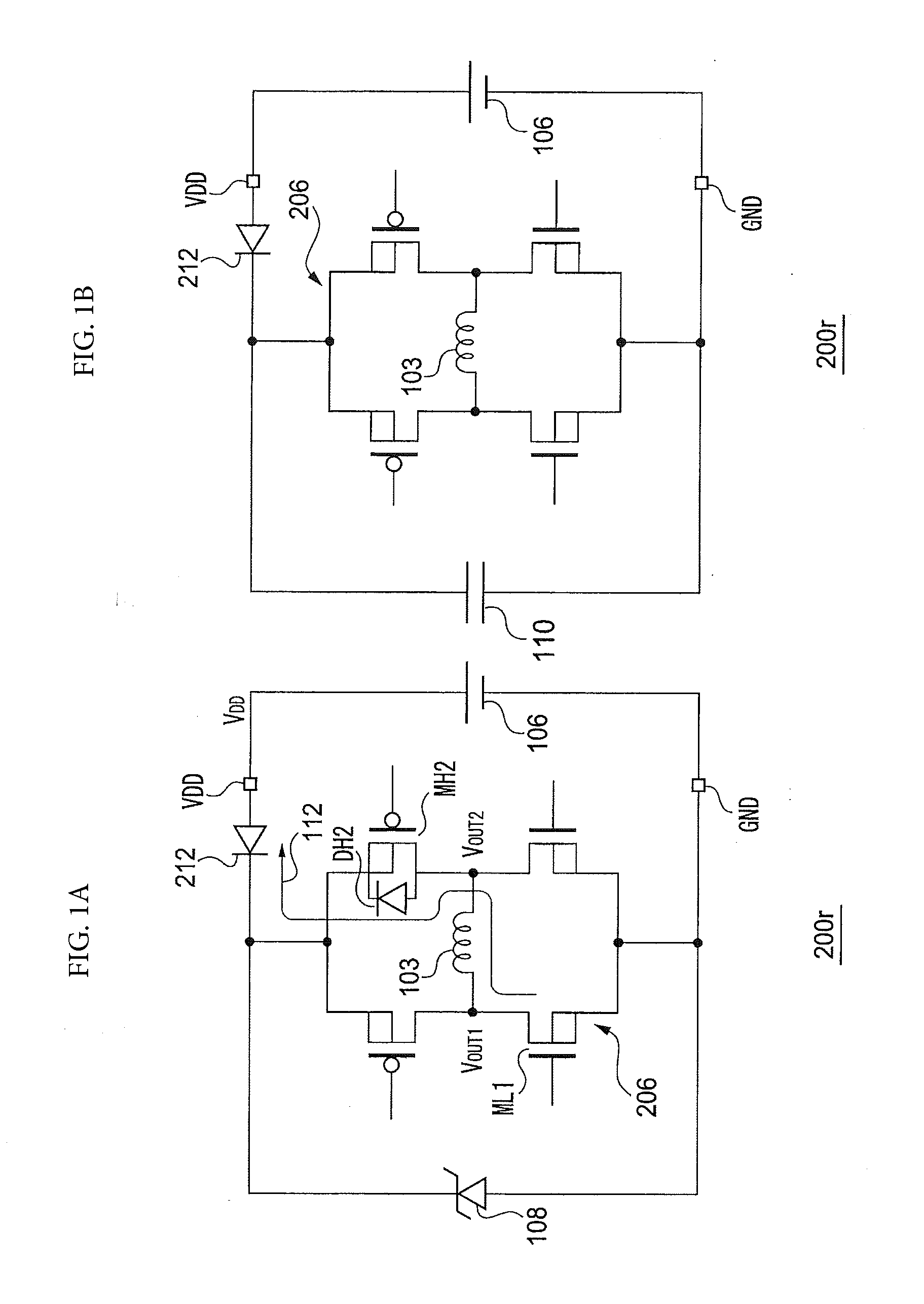
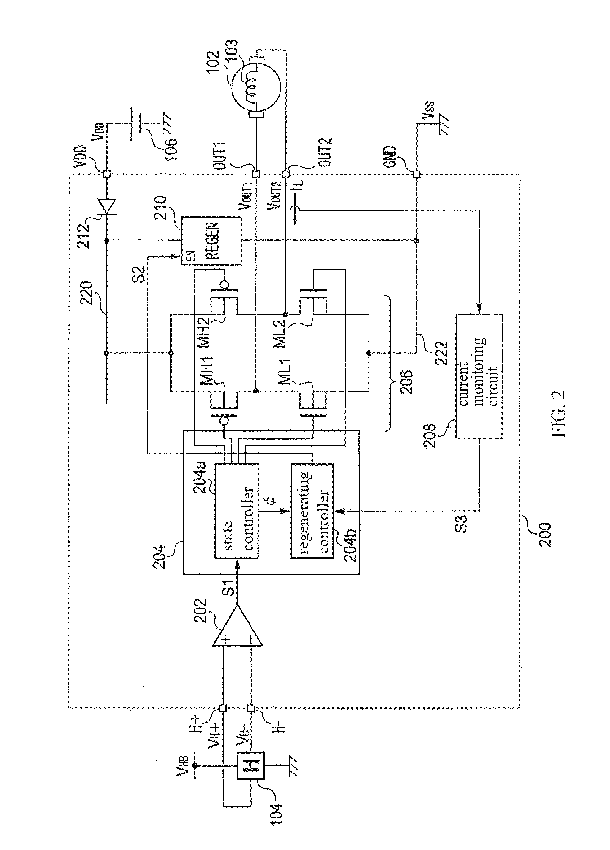
[0054]The present invention is described hereinbelow based on preferred embodiments thereof by referencing to the appended drawings. Like or equivalent constituting elements, components and processes across various drawings are designated with the same or similar reference symbols, and repeated description thereof may be omitted where suitable. Also, the embodiments are provided for illustrative purposes and should not be construed to limit the scope of the claimed invention, while not all the features or combinations thereof are necessarily the essence of the claimed invention.

[0055]In this specification, the description regarding the status that “a component A is connected with / to a component B” includes not only the physical and direct connection between the component A and the component B, but also the indirect connection between the component A and the component B; as long as such indirect connection does not substantially affect the electric connection status therebetween or t...


PUM


Abstract

The present invention inhibits the voltage jump of a source voltage or an output voltage by an approach which is different from a conventional one. A logic circuit allows an H bridge circuit to be shifted among a plurality of states in a specific sequence. A compulsory regenerating circuit is configured to be switched between an enabled state and a disabled state; while being in the enabled state, the current that flows in from a ground line via the H bridge circuit and a motor coil to a power line back-flows to the ground line.

Description

CROSS REFERENCE TO RELATED APPLICATIONS[0001]The present invention claims priority under 35 U.S.C. §119 to Japanese Application No. 2014-212983 filed Oct. 17, 2014, the entire content of which is incorporated herein by reference.BACKGROUND[0002]In recent years, with the aim of speeding up the personal computers or work stations, the operating speed of large scale integrated circuits (LSIs) for use in calculation processing, such as central processing units (CPUs) and digital signal processors (DSPs) continues to increase. The heat generated by such LSIs also increases with the increase in the operating speed (that is, the increase in clock frequency) thereof. The heat generated from the LSI causes the thermal runaway of the LSI itself or affects the peripheral circuits. Therefore, the appropriate cooling down of the heat generators such as the LSI (hereinafter, LSI, collectively) becomes a critical technology. As one example of the technology for cooling down the LSI, an air-cooled ...

Claims


Application Information

Patent Timeline
IPC IPC(8): H02P6/14H02K11/00H02P6/00
CPCH02P6/14H02K11/0021H02P6/001H02P6/008
Inventor GOHARA, YUKIMISHIMA, TOMOFUMI
Owner ROHM CO LTD
Why Eureka
Try Eureka