Welding method for copper and steel and application thereof

Inactive Publication Date: 2016-05-05
ZHUJI SIBEIDA MACHINERY CO LTD
View PDF4 Cites 6 Cited by
  • Summary
  • Abstract
  • Description
  • Claims
  • Application Information

AI Technical Summary

Benefits of technology

[0022]In the welding process, considering the situation that the heat conduction rate of the copper material is much higher than that of the steel material, that is the heat dissipation of the copper material is faster than that of the steel material, by setting the position of the heating part for providing heat for welding, the top end of the heating part is shifted to the direction where the copper material is. Thus, the heat distributed to the end to be welded of the copper material is more than the heat distributed to the end to be welded of the steel material, and the two materials achieve a synchronous melting state and further fuse mutually boundlessly to form a weld seam without leakages and cracks.
[0023]In addition, the liquid molten pool is used for melting the welding material and then forming the weld seam, thereby avoiding the problem of incomplete fusion of a welding wire caused by unstable arc voltage due to the existen

Problems solved by technology

Although aluminum has good plasticity, the strength and the weight thereof cannot meet the general requirements in the field of refrigeration or air conditioners, and the aluminum metal can only be used for replacing copper in a small part.
As for the welding of the two different metals, due to different melting points, different heat conduction rates, and different metallurgical structures in a liquid state, it is very difficult to realize solderless welding directly.
Particularly, the solder with a melting point lower than that of a base material is commonly added for welding, but the way of adding the solder is high in cost and has the risk that the welding material is re-molten at a firs

Method used


Image

  • Welding method for copper and steel and application thereof
  • Welding method for copper and steel and application thereof
  • Welding method for copper and steel and application thereof

Examples


embodiment 1

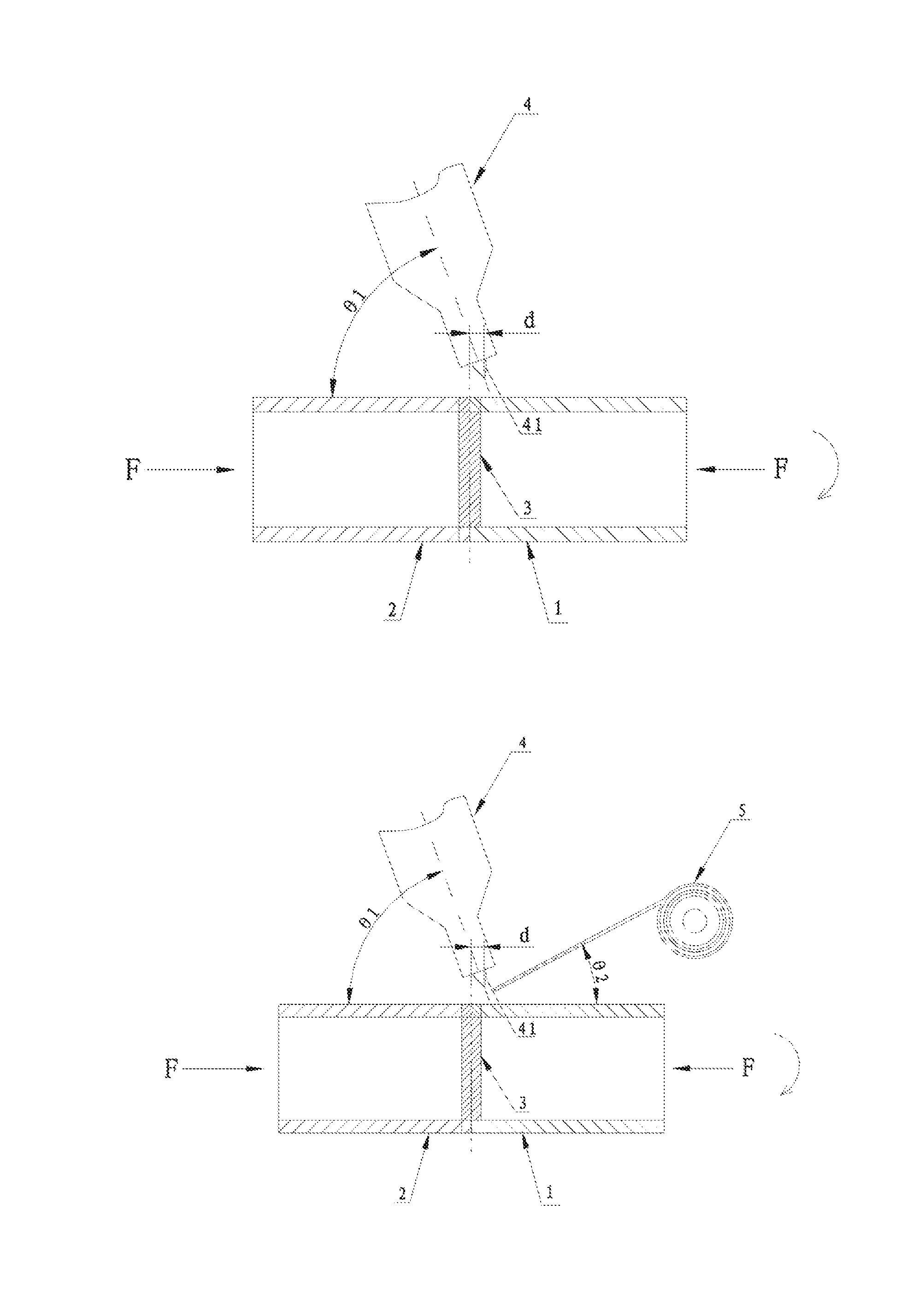
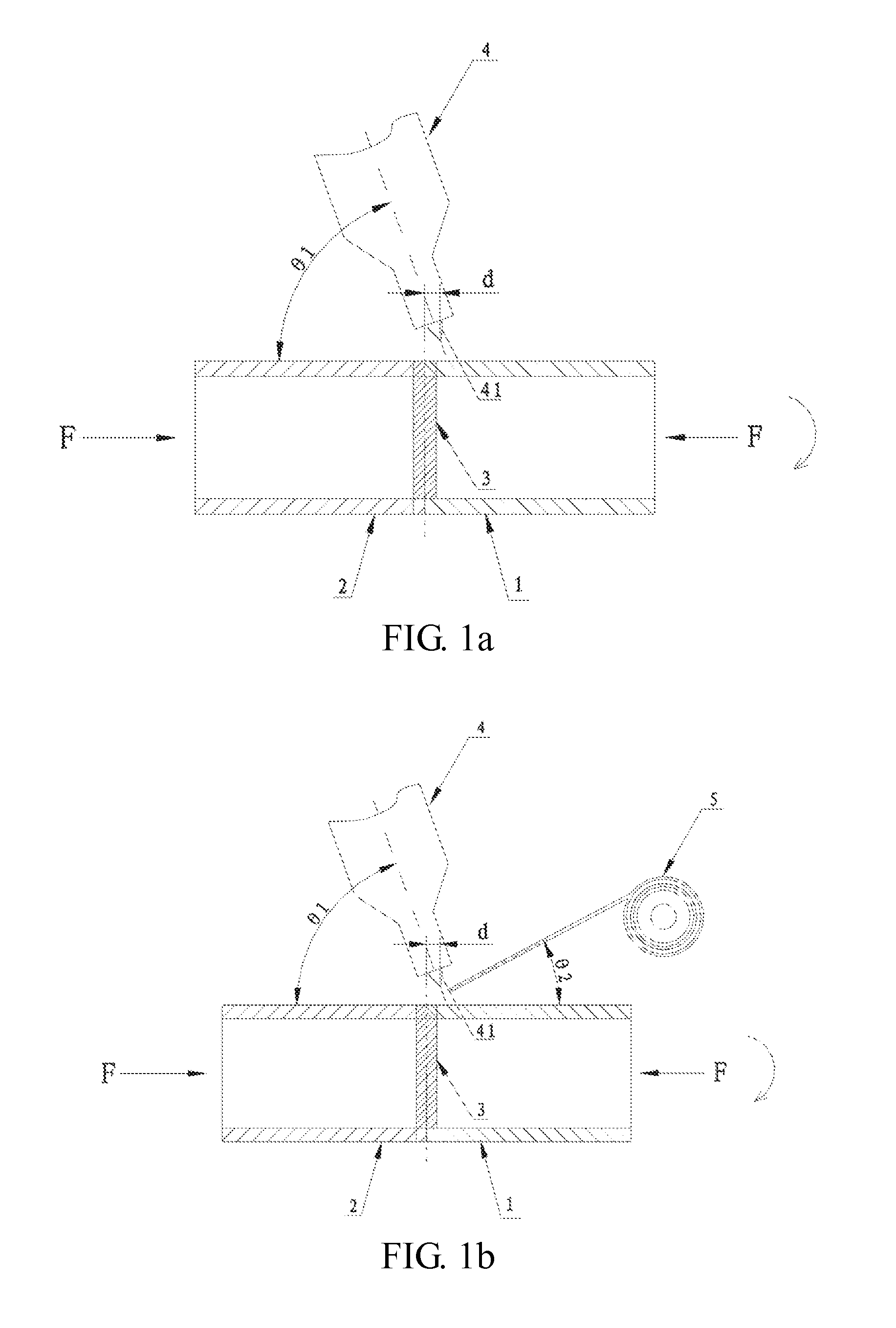
[0036]In this embodiment, a welding method for copper and steel is used for welding a gas inlet pipe and a gas outlet pipe of a liquid storage device for a compressor, as shown in FIG. 3A and FIG. 3B, respectively. The difference is that, in FIG. 3A, the end to be welded of a copper material 1 and the end to be welded of a steel material 2 are sleeve connected, the shift distance is a component of the distance from the top end of the heating part to an end surface of the end to be welded of the material which is arranged at the outside by sleeve connection in an axial direction of the copper material. In FIG. 3B, the end to be welded of a copper material 1 and the end to be welded of a steel material 2 are butt connected, and the shift distance is the component of the distance from the top end of the heating part to the butt connecting surface in the axial direction of the copper material. The embodiment will be described in detail below by taking the production principle diagram in...

embodiment 2

[0052]In the embodiment, a welding method for copper and steel is used for welding a gas inlet pipe and a gas outlet pipe of a gas-liquid separator for a central air conditioner, as shown in FIG. 4a and FIG. 4b. The embodiment is basically the same as embodiment 1 and the changes thereof, and the differences are as follows:

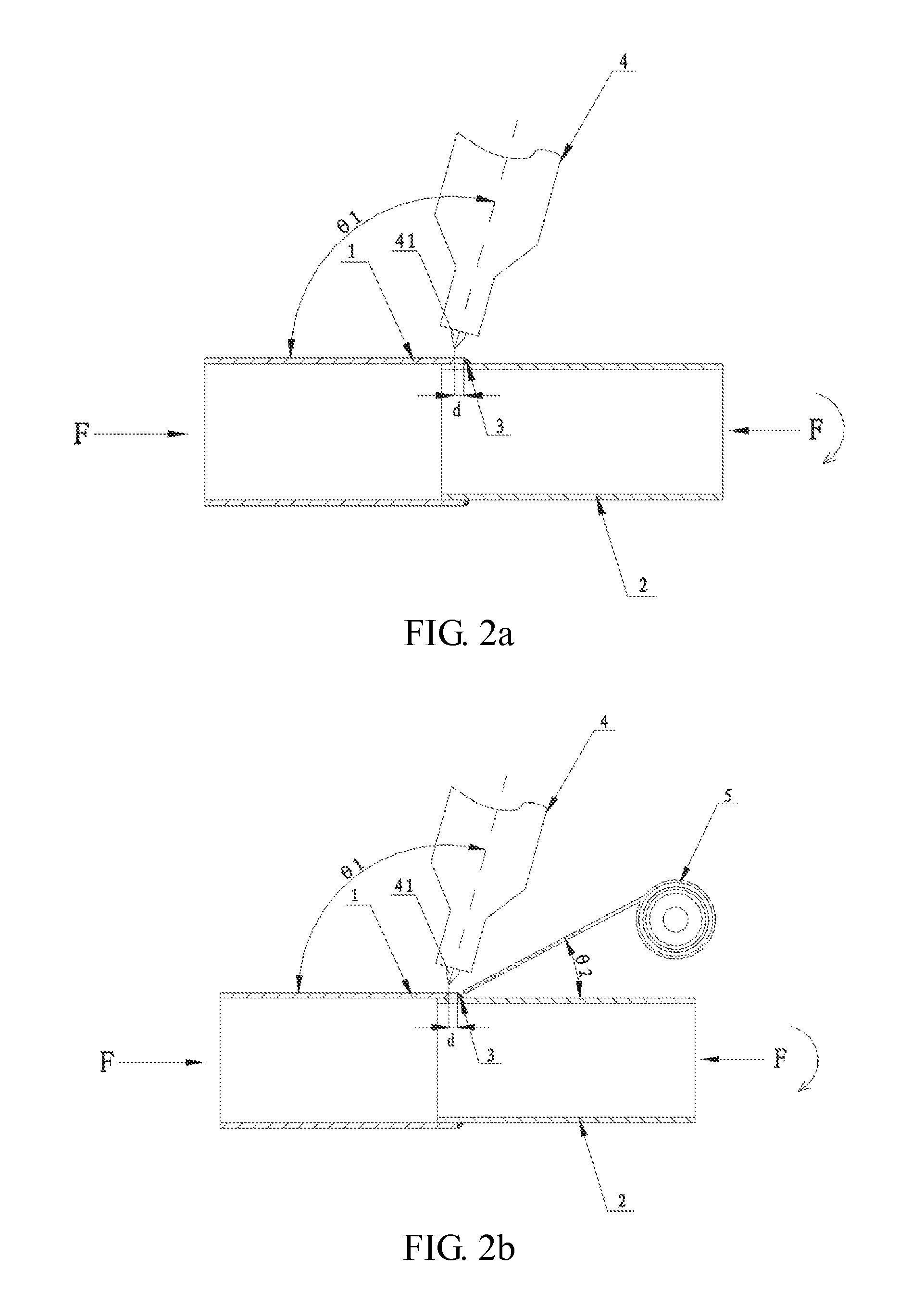
[0053]In FIG. 4a and FIG. 4b, the end to be welded of the copper material 1 and the end to be welded of the steel material 2 are butt welded, and the shift distance d is a component of the distance from the top end of the heating part 41 to the butt connecting surface in the axial direction of the copper material 1. The top end of the heating part 41 is shifted towards the copper material 1, and the shift distance d is 0.1 mm. It can be seen from Table 1 that when the shift distance d is 0.1 mm, the diameter of the grains formed after welding is only 0.08 mm, and the testing shows that various indexes of the weld seam 3 can meet the requirements. However, the inve...

embodiment 3

[0056]In the embodiment, a welding method for copper and steel is used for welding an exhaust pipe, a gas suction outer pipe and a gas suction inner pipe of a refrigeration compressor, as shown in FIG. 5a, FIG. 5b and FIG. 5c. The embodiment is basically the same as embodiment 1 and the changes thereof, and the differences are as follows.

[0057]In FIG. 5a, the end to be welded of the steel material 2 is sleeve connected inside the end to be welded of the copper material 1, and the shift distance d is a component of the distance from the top end of the heating part to the end surface at the end to be welded of the copper material 1 in the axial direction of the copper material 1. In FIG. 5b and FIG. 5c, the end to be welded of the copper material 1 and the end to be welded of the steel material 2 are butt welded, and the shift distance d is the component of the distance from the top end of the heating part to the butt connecting surface in the axial direction of the copper material. I...


PUM

PropertyMeasurementUnit
Angleaaaaaaaaaa
Distanceaaaaaaaaaa

Abstract

A welding method for copper and steel and application thereof is described herein. The welding method includes the following steps: butt connecting or sleeve connecting an end to be welded of a copper material with an end to be welded of a steel material; and welding and connecting the end to be welded of the copper material and the end to be welded of the steel material by a heating part of a heat supply device under the protection of a shielding gas, wherein the top end of the heating part is shifted towards the copper material, and the end to be welded of the copper material and the end to be welded of the steel material are simultaneously molten and further fuse mutually.

Description

BACKGROUND OF THE INVENTION[0001]1. Field of the Invention[0002]This invention relates to the field of welding of pipes and materials and, more particularly, relates to a welding method for copper and steel and application thereof.[0003]2. Description of the Related Art[0004]With development of society, national energy-saving and consumption-reducing policies are promoted continuously. In every industry, resources are continuously saved, and energy consumption is continuously reduced. In the refrigeration industry, a precious metal with good plasticity and strength, namely “copper”, has always been used as a main raw material for production and processing. In the development course of the industry in these years, many scientists performed research work on substitution of various materials, and it was well known that aluminum was used for replacing copper. Although aluminum has good plasticity, the strength and the weight thereof cannot meet the general requirements in the field of r...

Claims


Application Information

Patent Timeline
IPC IPC(8): B23K9/173B23K35/30B23K9/23B23K35/02
CPCB23K9/173B23K35/0261B23K35/3033B23K2203/22B23K35/3006B23K9/232B23K35/302B23K9/0282B23K9/167B23K2101/06B23K2103/22
Inventor SI, ZHUANGWEI
Owner ZHUJI SIBEIDA MACHINERY CO LTD
Why Eureka
Try Eureka