Roller Traction Drive System for an Aircraft Drive Wheel Drive System

a technology of drive system and aircraft, which is applied in the direction of energy-saving operation measures, alighting gear, transportation and packaging, etc., can solve the problems of unattractive alternative to aircraft ground movement, the inability to use the main engine of the aircraft to move the aircraft during ground operations, and the crowded and congested airport facilities

Inactive Publication Date: 2016-05-05
WARNER ELECTRIC TECH +1
View PDF30 Cites 10 Cited by
  • Summary
  • Abstract
  • Description
  • Claims
  • Application Information

AI Technical Summary

Benefits of technology

[0006]It is a primary object of the present invention, therefore, to provide a highly efficient roller traction drive system that can be effectively integrated with a non-engine drive means actuated by the roller traction drive system in a an aircraft drive wheel drive system that moves the aircraft autonomously on the ground without reliance on the aircraft's main engines or external ground vehicles

Problems solved by technology

As air travel has increased over the past decades, airport facilities have become more crowded and congested.
As airline fuel costs, safety concerns, and regulations have increased, the airline industry is beginning to acknowledge that continuing to use an aircraft's main engines to move aircraft during ground operations is no longer the best option.
The delays, costs, and other challenges to timely and efficient aircraft pushback from airport terminals associated with the use of tugs and tow vehicles makes this type of aircraft ground movement an unattractive alternative to the use of an aircraft's main engines to move an aircraft on the ground.
Not only does such engine use consume fuel, it is also burns fuel inefficiently and produces engine exhaust that contains microparticles and other products of incomplete combustion.
Operating aircraft engines, moreover, are noisy, and the associated safety hazards of jet blast and engine ingestion in congested gate and ramp areas are significant concerns that cannot be overlooked.
None of the foregoing art, moreover, recognizes the significant improvements in drive means operating efficiency possible when gearing systems are replaced by roller-type drive systems to drive or actuate non-engine drive means that move aircraft during ground operations.
While gear systems can be used quite effectively with such drive systems, they require proper lubrication and may add undesirable weight to an aircraft wheel.

Method used


Image

  • Roller Traction Drive System for an Aircraft Drive Wheel Drive System
  • Roller Traction Drive System for an Aircraft Drive Wheel Drive System
  • Roller Traction Drive System for an Aircraft Drive Wheel Drive System

Examples


Embodiment Construction

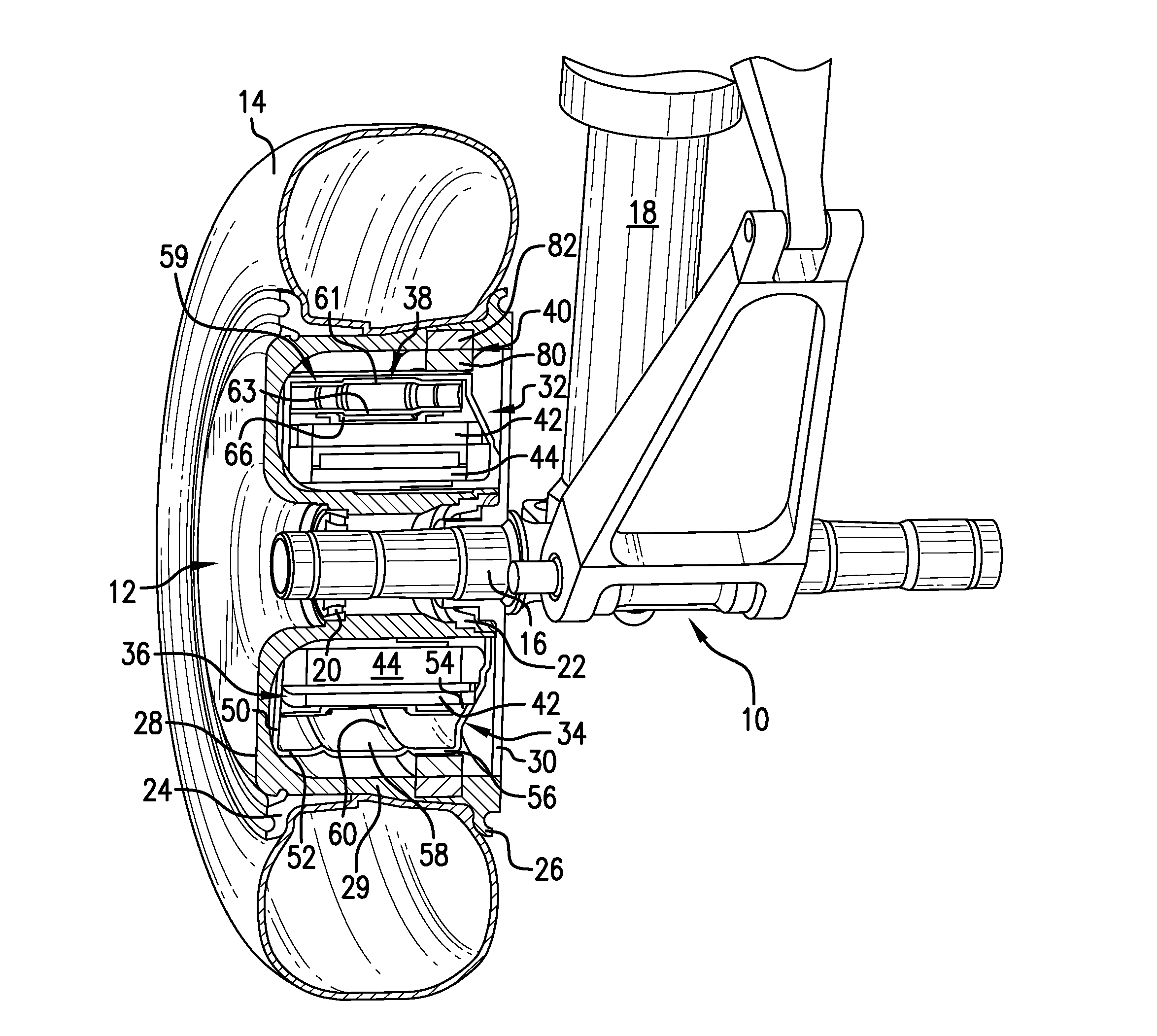
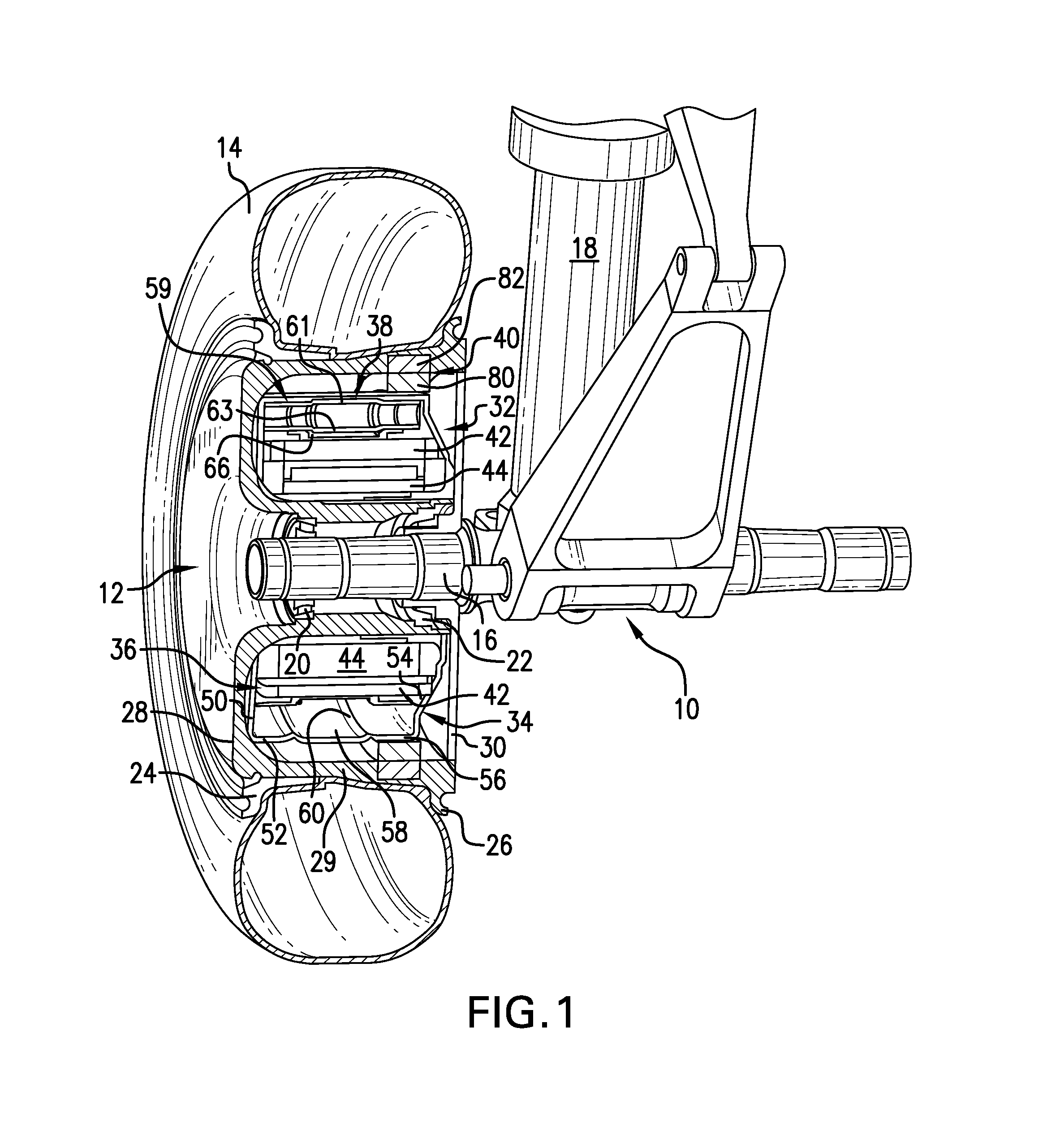
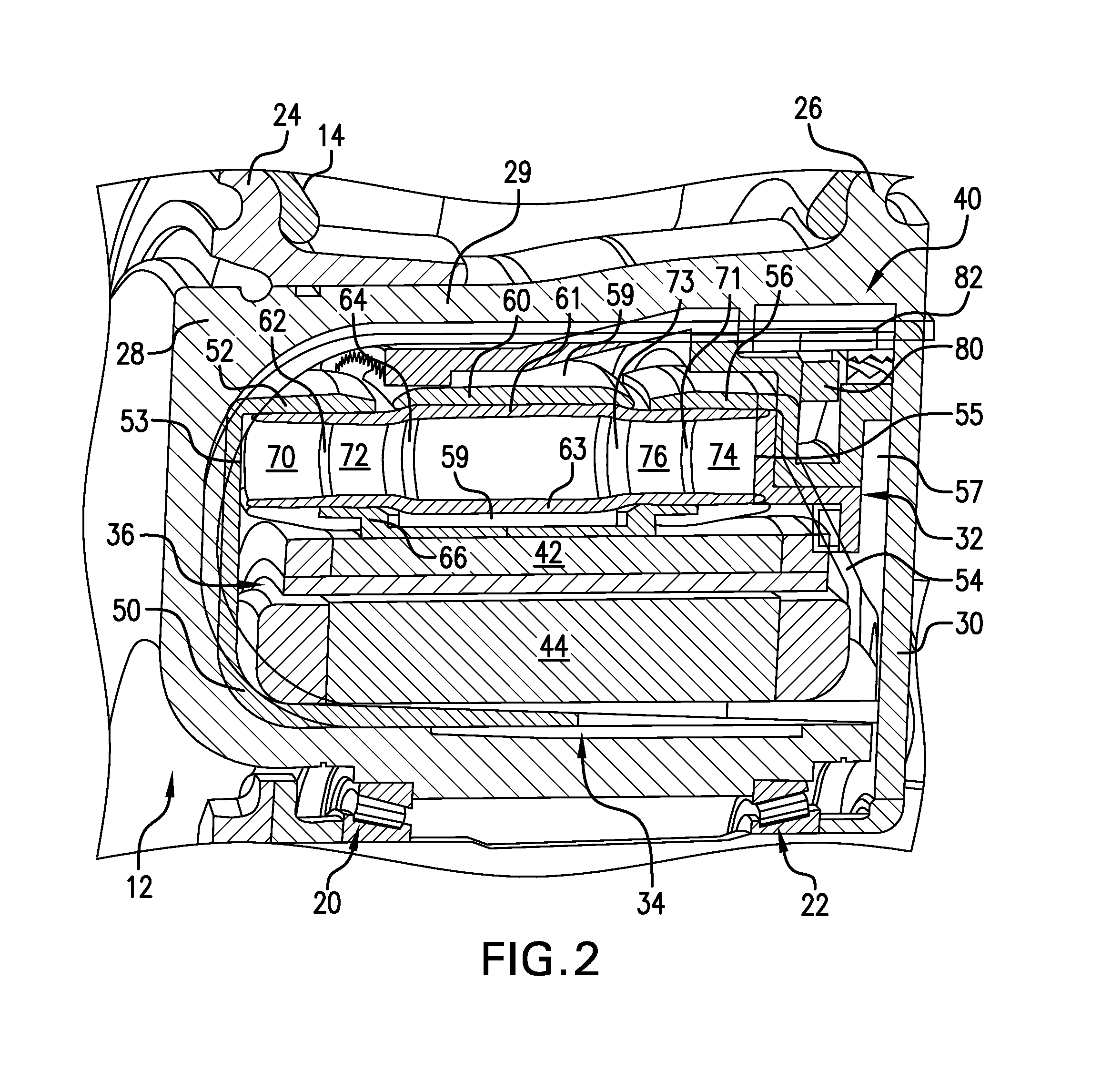
[0018]The benefits of being able to efficiently and safely move an aircraft during ground operations without reliance on the aircraft's main engines or external vehicles have long been recognized. Actually achieving these benefits, however, has proved challenging. Applicant's previously proposed aircraft wheel non-engine drive means have been demonstrated to effectively power drive wheels and move aircraft on the ground and, thus, can enable aircraft operators to achieve the advantages of autonomous ground movement. The present invention improves the capabilities of Applicant's original aircraft drive wheel drive system and expands the advantages possible when aircraft can be driven during ground operations by controllable onboard drive means independently of the aircraft's main engines and external ground vehicles. These advantages and improvements are achieved, in large part, by the design of an aircraft drive wheel drive system which integrally incorporates a roller traction driv...


PUM


Abstract

A roller traction drive system integral with a non-engine drive means and a clutch assembly in an aircraft drive wheel drive system capable of moving an aircraft autonomously on the ground is provided. The roller traction drive system is selectively activated by the clutch assembly into and out of actuating contact with the non-engine drive means to drive the aircraft drive wheel. Roller traction drive system components are made of materials designed to enable dry running and operation at the torques, drive means speeds, and reduction ratios required to actuate a drive means and drive a drive wheel for autonomous aircraft ground movement. Roller traction drive materials may be selected to maintain effective torque transfer between roller traction drive system components and the non-engine drive means as well as to minimize undesirable thermal expansion.

Description

TECHNICAL FIELD[0001]The present invention relates generally to roller traction drive systems and particularly to a roller traction drive system designed to actuate a non-engine drive means in an aircraft drive wheel drive system to move an aircraft autonomously during ground operations without use of the aircraft's main engines or external tow vehicles.BACKGROUND OF THE INVENTION[0002]As air travel has increased over the past decades, airport facilities have become more crowded and congested. Minimizing the time between the arrival of an aircraft and its departure to maintain an airline's flight schedule, and also to make a gate or parking location available without delay to an incoming aircraft, has become a high priority in the management of airport ground operations. The safe and efficient ground movement of a large number of aircraft simultaneously into and out of ramp and gate areas has become increasingly important. As airline fuel costs, safety concerns, and regulations have...

Claims


Application Information

Patent Timeline
Patent Type & Authority Applications(United States)
IPC IPC(8): B64C25/40
CPCB64C25/405Y02T50/80
Inventor COX, ISAIAH W.PERKINS, SCOTTSTOLTZE, DAVID
Owner WARNER ELECTRIC TECH
Why Eureka
Try Eureka