Fluid evaporation apparatus including fuel cells

a technology of evaporation apparatus and fuel cells, which is applied in the direction of evaporator regulation/control, separation process, treatment water nature, etc., can solve the problems of inability to operate in high winds or extreme cold weather, large amount of water or other fluids in undesired locations, and inability to dispose of collected water in the pond

Inactive Publication Date: 2016-05-05
ALSHEHRI FARIS FAYIZ
View PDF3 Cites 2 Cited by
  • Summary
  • Abstract
  • Description
  • Claims
  • Application Information

AI Technical Summary

Problems solved by technology

In instances both by nature and by man, water or other fluids may collect in large amounts in undesired locations, such as ponds, swamps, roadways, etc.
The problem with this arrangement is that the collected water in the pond must be disposed of.
First, they cannot operate in high winds or extreme cold weather.
Second, the mist still allows for ground saturation in areas of sustained winds which requires system shutdown.
Third, these systems can be cumbersome to set up, maintain and move.
Fourth, these evaporation systems are limited to impoundment pond operations.
Once a drilling site has been reclaimed, the excess water ends up in a storage tank which current evaporation systems cannot access.
In another example, still or stagnant water, such as rain or storm water, swamp water or the like is historically difficult to eliminate or remove via evaporation.
Still or stagnant water may further pose a risk to people and / or traffic flow of vehicles after a storm or weather event.
Draining swamps and still or stagnant water may cause people to get injured, drown, or cause disease, such as malaria or hay fever.

Method used


Image

  • Fluid evaporation apparatus including fuel cells
  • Fluid evaporation apparatus including fuel cells
  • Fluid evaporation apparatus including fuel cells

Examples


Embodiment Construction

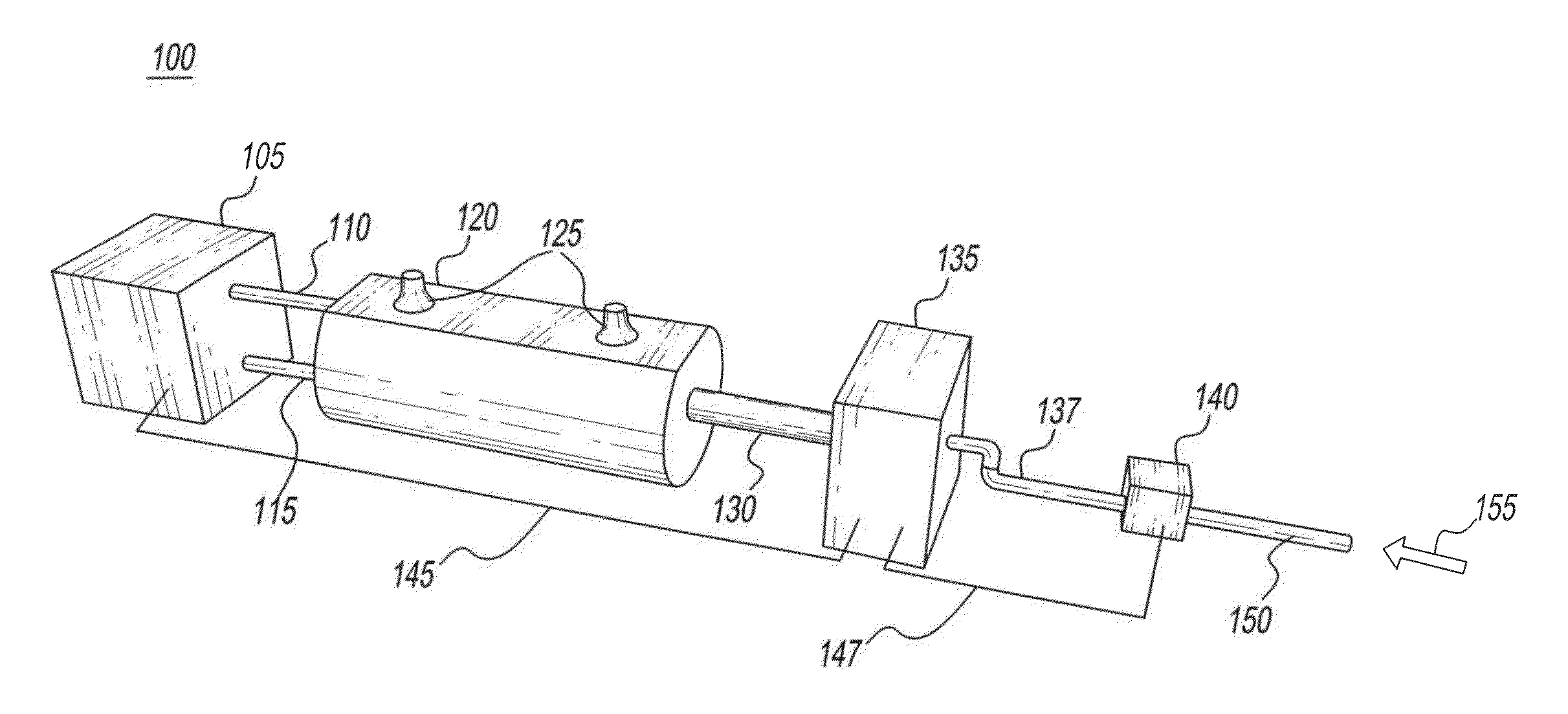
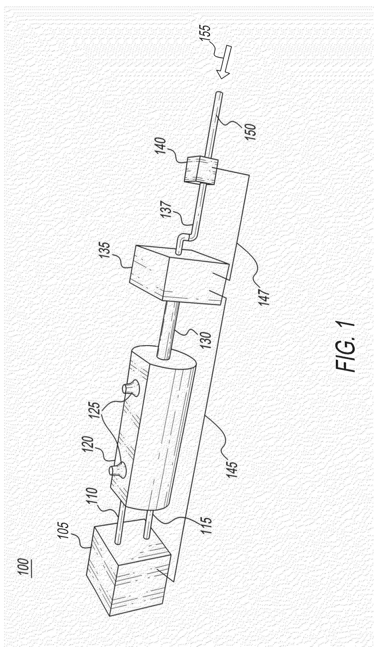
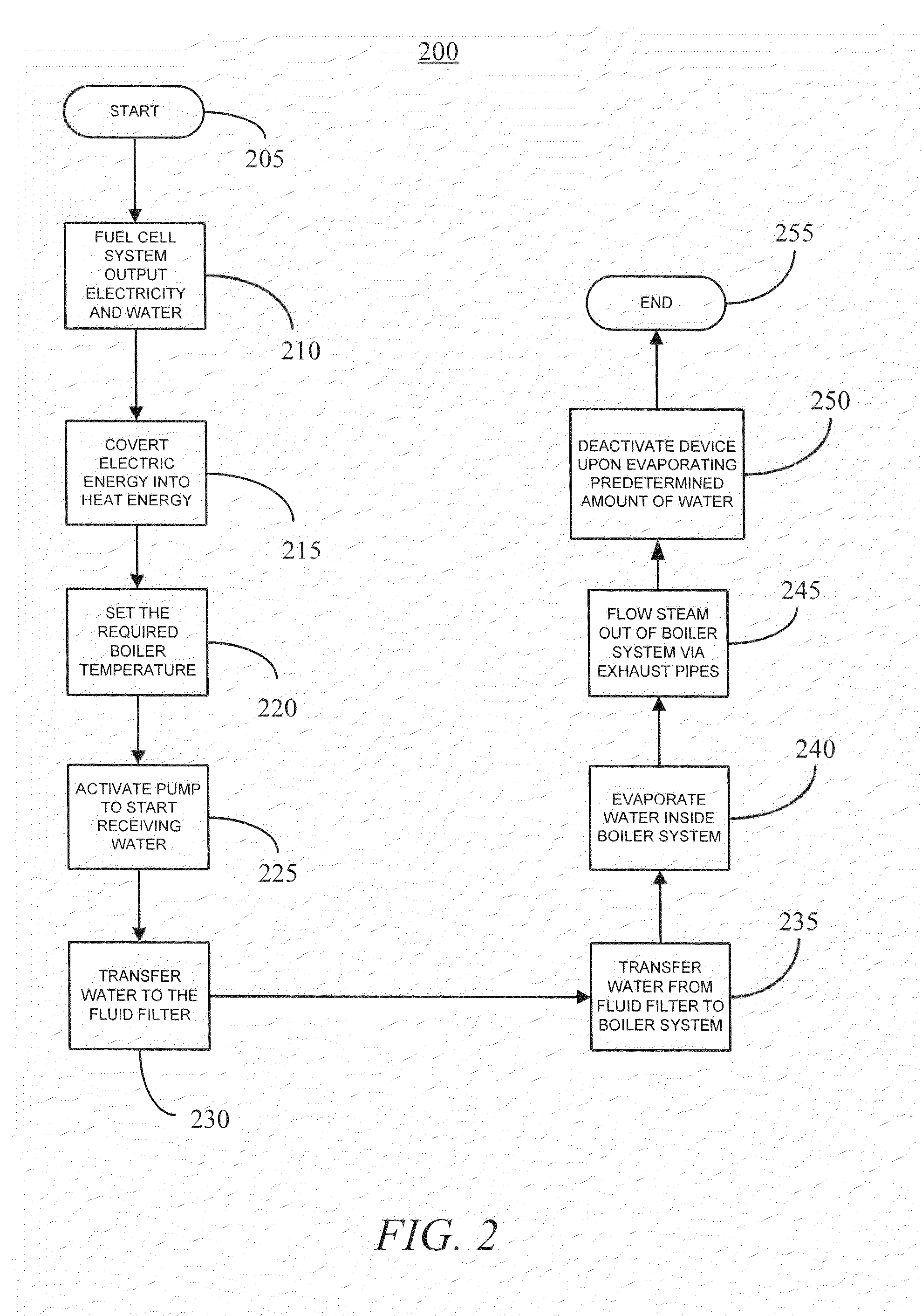
[0022]Referring now to the drawings, wherein like reference numerals designate identical or corresponding parts throughout the several views, a fluid evaporator includes fuel cells that provide the benefits of using sustainable environmental energy, saving time and money, and supporting governments and organizations with environmental projects regarding still or stagnant liquid / water removal.

[0023]An additional benefit may be for the fluid evaporator to provide certain areas of the world lacking in proper rainwater drainage networks to have a device which can readily remove any still or stagnant fluids / liquid. Other applications of the device may include swimming pools, swamp drainage to reduce disease, or removing still or stagnant fluids / water from roadways which may affect traffic.

[0024]Fuel cells are electrochemical devices that convert a fuel's chemical energy directly to electrical energy with high efficiency, with no moving parts. A fuel cell can produce electricity continuou...


PUM

PropertyMeasurementUnit
grain sizeaaaaaaaaaa
temperatureaaaaaaaaaa

Abstract

A fluid evaporation apparatus utilizes a sustainable energy source via fuel cells to evaporate large quantities of water or liquid within a predetermined time frame. This water or liquid may be in difficult to reach locations and thus, the apparatus may be mobile and sized based on any required application large or small. The apparatus includes an electrochemical power source and a fluid evaporator electrically connected to the electrochemical power source. The apparatus also includes a fluid filter electrically connected to the electrochemical power source and a pump electrically connected to the electrochemical power source. The electrochemical power source, the fluid evaporator, the fluid filter, and the pump are fluidly connected to suction and evaporate a fluid source. The electrochemical power source, the fluid evaporator, the fluid filter, and the pump are electronically actuated by a controller.

Description

GRANT OF NON-EXCLUSIVE RIGHT[0001]This application was prepared with financial support from the Saudia Arabian Cultural Mission, and in consideration therefore the present inventor(s) has granted. The Kingdom of Saudi Arabia a non-exclusive right to practice the present invention.BACKGROUND[0002]1. Field of the Disclosure[0003]This disclosure relates to fluid evaporation devices including fuel cells and more specifically to a device for increasing the evaporation of fluids contained in still or stagnant locations while using a sustainable power source.[0004]2. Description of the Related Art[0005]The “background” description provided herein is for the purpose of generally presenting the context of the disclosure. Work of the presently named inventors, to the extent it is described in this background section, as well as aspects of the description which may not otherwise qualify as prior art at the time of filing, are neither expressly or impliedly admitted as prior art against the pre...

Claims


Application Information

Patent Timeline
Patent Type & Authority Applications(United States)
IPC IPC(8): C02F1/04C02F1/00H01M8/10
CPCC02F1/048H01M8/1018C02F2103/365H01M2250/10H01M2008/1095C02F1/004B01D1/0017B01D1/0082C02F1/001C02F1/16C02F1/283H01M8/04291Y02B90/10Y02E60/50
Inventor ALSHEHRI, FARIS FAYIZ
Owner ALSHEHRI FARIS FAYIZ
Why Eureka
Try Eureka