Hydrogen production system and method for producing hydrogen

a hydrogen production system and hydrogen production method technology, applied in the direction of energy input, electrolysis components, electrolysis processes, etc., can solve the problem that the thermal energy generated when the hydrogen is compressed is not effectively utilized to improve the hydrogen production efficiency, and achieve the effect of reducing the amount of heat input and improving the hydrogen production efficiency

Active Publication Date: 2016-05-05
KK TOSHIBA
View PDF3 Cites 10 Cited by
  • Summary
  • Abstract
  • Description
  • Claims
  • Application Information

AI Technical Summary

Benefits of technology

[0013]Embodiments of the present invention have been implemented in view of the above circumstances and have an object to provide a hydrogen production technique capable of reducing an amount of heat input concerning hydrogen production to improve hydrogen production efficiency.

Problems solved by technology

In conventional techniques, cooling is performed when hydrogen is compressed, and thermal energy generated when the hydrogen is compressed is not effectively utilized to improve hydrogen production efficiency (which is obtained by dividing an amount of hydrogen production or an amount of combustion heat of the produced hydrogen by an amount of heat input).

Method used


Image

  • Hydrogen production system and method for producing hydrogen
  • Hydrogen production system and method for producing hydrogen
  • Hydrogen production system and method for producing hydrogen

Examples


first embodiment

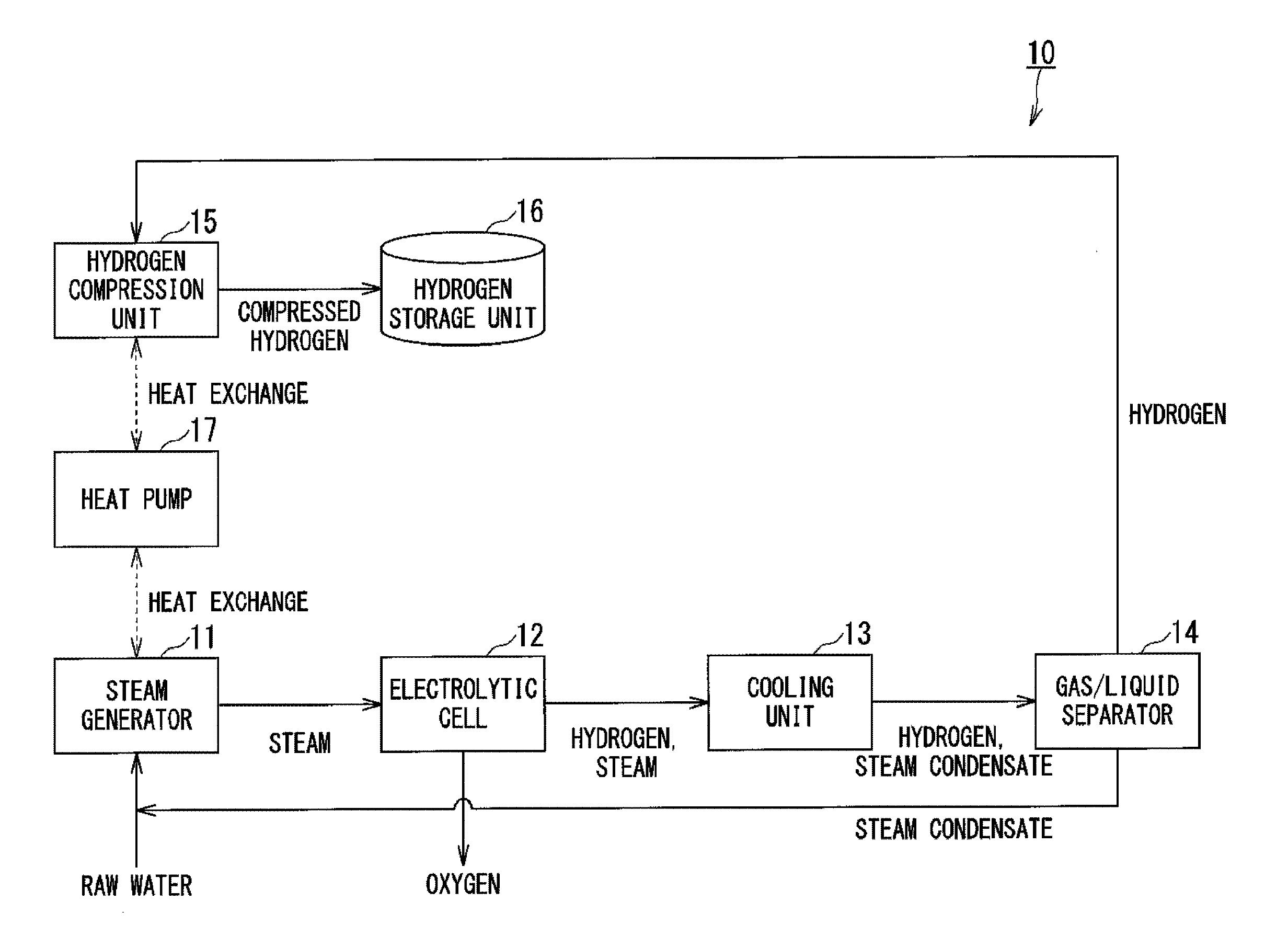
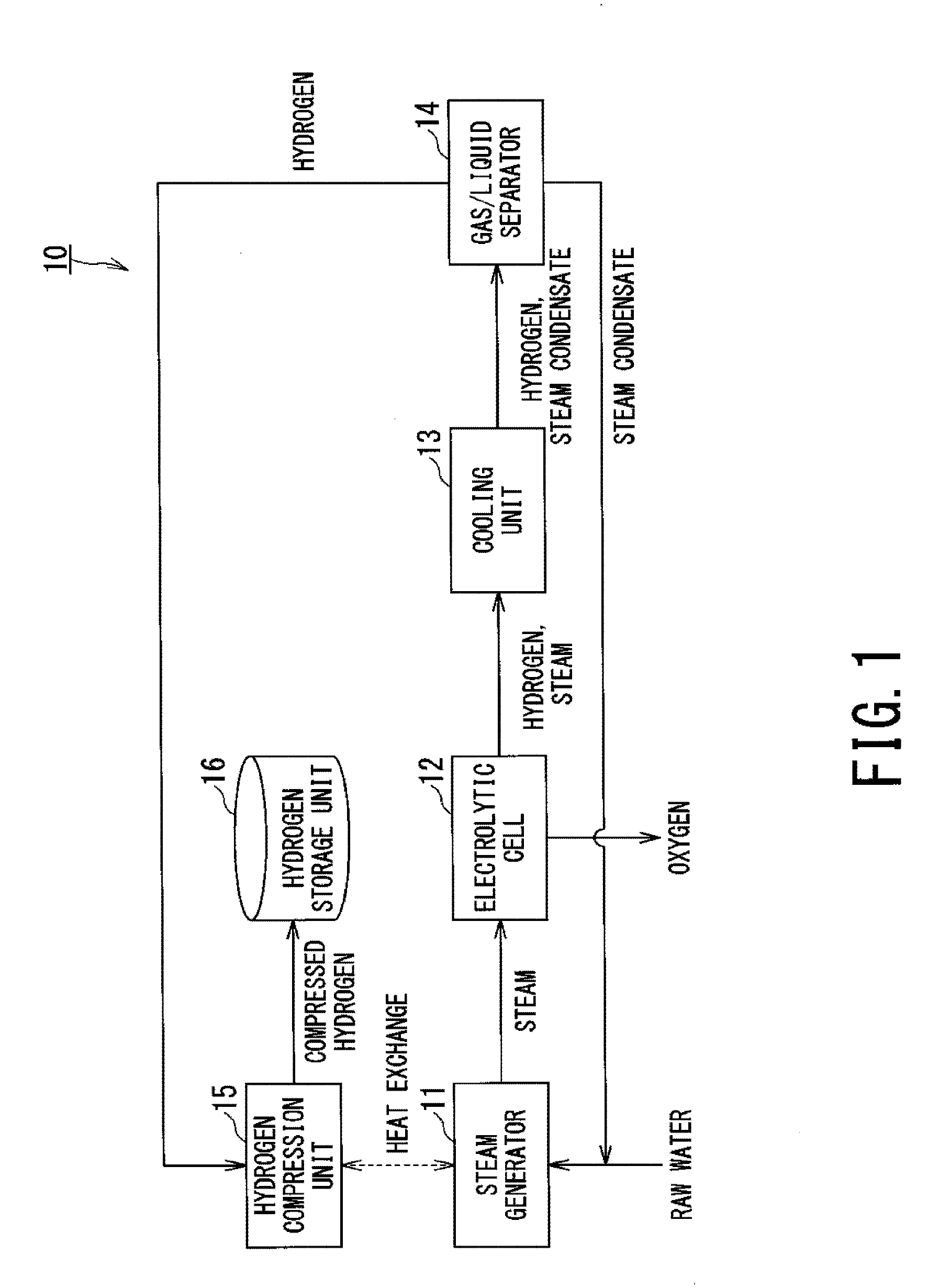
[0019]As illustrated in FIG. 1, a hydrogen production system 10 according to a first embodiment includes: a steam generator 11 heating supplied raw water and generating steam; an electrolytic cell 12 that receiving the steam and generating hydrogen and oxygen through a high temperature electrolysis; a cooling unit 13 cooling an unreacted part of the steam in the high temperature electrolysis and changing the unreacted part of the steam into steam condensate; a gas / liquid separator 14 that performing gas / liquid separation on the generated hydrogen and the generated steam condensate; a hydrogen compression unit 15 compressing the separated hydrogen and transmitting thermal energy generated when the hydrogen is compressed, to the raw water; and a hydrogen storage unit 16 storing the compressed hydrogen.

[0020]The steam generator 11 heats and evaporates the supplied raw water, and increases a temperature of the steam up to a temperature (700° C. or higher) suitable for the high temperatu...

second embodiment

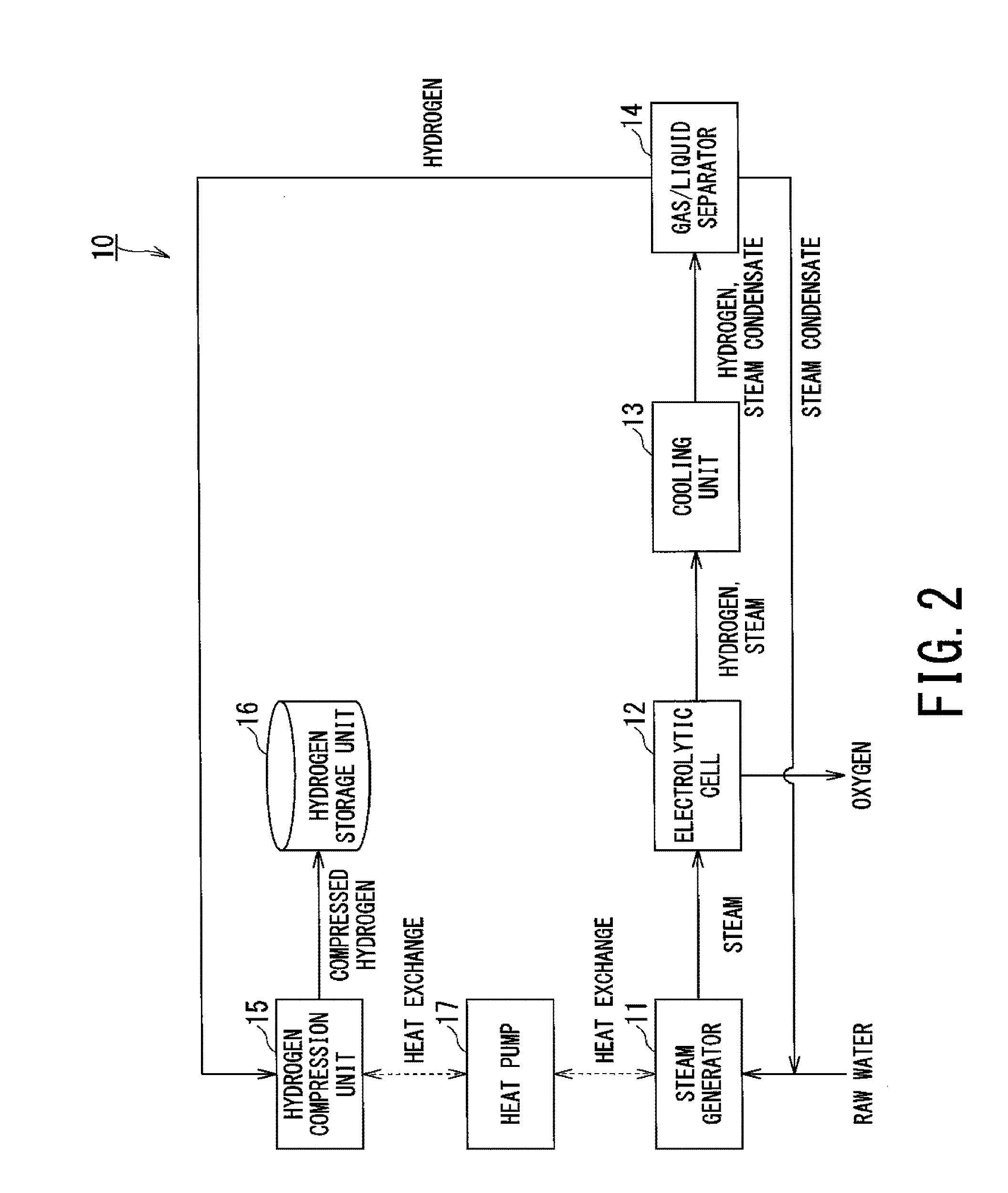
[0044]FIG. 2 is a configuration diagram of a hydrogen production system 10 according to a second embodiment. Configurations and portions corresponding to those of the first embodiment are denoted by the same reference signs, and overlapping description is omitted.

[0045]The hydrogen production system 10 of the second embodiment is different from that of the first embodiment in that a heat pump 17 that compresses and expands a refrigerant to thereby transfer thermal energy is further provided between the hydrogen compression unit 15 and the steam generator 11 and that the hydrogen compression unit 15 transmits the thermal energy generated when the hydrogen is compressed, to the raw water with the intermediation of the refrigerant.

[0046]The heat pump 17 forms a circulation loop for circulating the refrigerant, and includes a compressor and an expansion valve on the circulation loop. The heat pump 17 compresses and expands the refrigerant to thereby transfer the thermal energy from a lo...


PUM

PropertyMeasurementUnit
temperatureaaaaaaaaaa
temperaturesaaaaaaaaaa
pressureaaaaaaaaaa

Abstract

A hydrogen production system includes: a steam generator heating supplied raw water and generating steam; an electrolytic cell receiving the steam and generating hydrogen and oxygen through a high temperature electrolysis; a cooling unit cooling an unreacted part of the steam in the high temperature electrolysis and changing the unreacted part of the steam into steam condensate; a gas/liquid separator performing gas/liquid separation on the generated hydrogen and the generated steam condensate; a hydrogen compression unit compressing the separated hydrogen and transmitting thermal energy generated when the hydrogen is compressed, to the raw water; and a hydrogen storage unit storing the compressed hydrogen.

Description

CROSS-REFERENCE TO RELATED APPLICATION[0001]This application is based upon and claims the benefit of priority from Japanese Patent Application No. 2014-223044, filed on Oct. 31, 2014, the entire contents of which are incorporated herein by reference.BACKGROUND[0002]1. Technical Field[0003]Embodiments described herein relate generally to a hydrogen production technique for producing hydrogen by using a high temperature electrolysis.[0004]2. Description of the Related Art[0005]Realization of a hydrogen energy society using hydrogen as an energy medium is attracting attention. A high temperature electrolysis method is widely known as one of techniques for producing hydrogen. The high temperature electrolysis method is a method for generating hydrogen and oxygen through an electrolysis of high temperature steam.[0006]This method has an advantage that, because steam is electrolyzed in a high temperature environment, an amount of electricity necessary for the electrolysis can be reduced c...

Claims


Application Information

Patent Timeline
Patent Type & Authority Applications(United States)
IPC IPC(8): C25B1/04
CPCC25B1/04C25B15/08C25B9/73Y02E60/36Y02P20/129Y02P20/133
Inventor OOMURA, HISAOYAMADA, KAZUYAMAKINO, SHINICHIWATANABE, HISAOFUJIWARA, SEIJIKASAI, SHIGEO
Owner KK TOSHIBA
Why Eureka
Try Eureka