
Method, system, and fuel injector for multi-fuel injection with pressure intensification and a variable orifice

a multi-fuel injection and pressure intensification technology, applied in liquid fuel feeders, machines/engines, mechanical devices, etc., can solve problems such as emissions, gasoline/ethanol and diesel fuel without pre-treatment, and many problems to be solved, so as to achieve low viscosity fuels, low viscosity, and low viscosity

Inactive Publication Date: 2016-05-05
QUANTLOGIC CORP +1
View PDF0 Cites 11 Cited by
  • Summary
  • Abstract
  • Description
  • Claims
  • Application Information

AI Technical Summary

Benefits of technology

The patent text discusses a method for using diesel fuel to boost the pressure of low viscosity fuels, such as gasoline and ethanol. This allows for high pressure injection, which leads to improved engine performance and reduced emissions. The method also involves the use of a novel internal pressure intensifier and the ability to generate variable spray patterns for different injection timings and engine loads. Overall, the patent text describes a way to optimize the performance and efficiency of gasoline and diesel engines.

Problems solved by technology

Due to its intrinsic non-homogeneous characteristics of fuel-air mixture formation, it is often contradictory to simultaneously reduce soot and NO sub(x)formation in a conventional diesel engine.
However, many issues remain to be solved to control the ignition timing, the duration of combustion, the heat release rate of combustion for HCCI and PCCI engines for various load conditions.
A key challenge for mixed-mode combustion with conventional fix-angle multi-hole nozzle is surface wetting for early injections.
However, researchers find that, even with smaller jets for very earlier injections, the conventional multiple jets spray still tend to wet the piston top and thus could cause emission issues such as hydrocarbon and mono-dioxide (SAE paper 2008-01-2400).
While port injection of gasoline / ethanol only demands low pressure gasoline fuel injection systems, engine experiment data also demonstrated high HC and CO emissions.
Due to lacking a practical dual-fuel injector for direct injection applications, on-demand separately direct injection of both gasoline / ethanol and diesel fuel without pre-blending is rare in literature.
Conventional direct fuel injections for low viscosity fuels such as gasoline and ethanol can only be done through early injection using relatively low pressure generally below 200 bars, and this is sufficient for most direct injection gasoline engines due to the low compression ratios.

Method used


Image

  • Method, system, and fuel injector for multi-fuel injection with pressure intensification and a variable orifice
  • Method, system, and fuel injector for multi-fuel injection with pressure intensification and a variable orifice
  • Method, system, and fuel injector for multi-fuel injection with pressure intensification and a variable orifice

Examples


Embodiment Construction

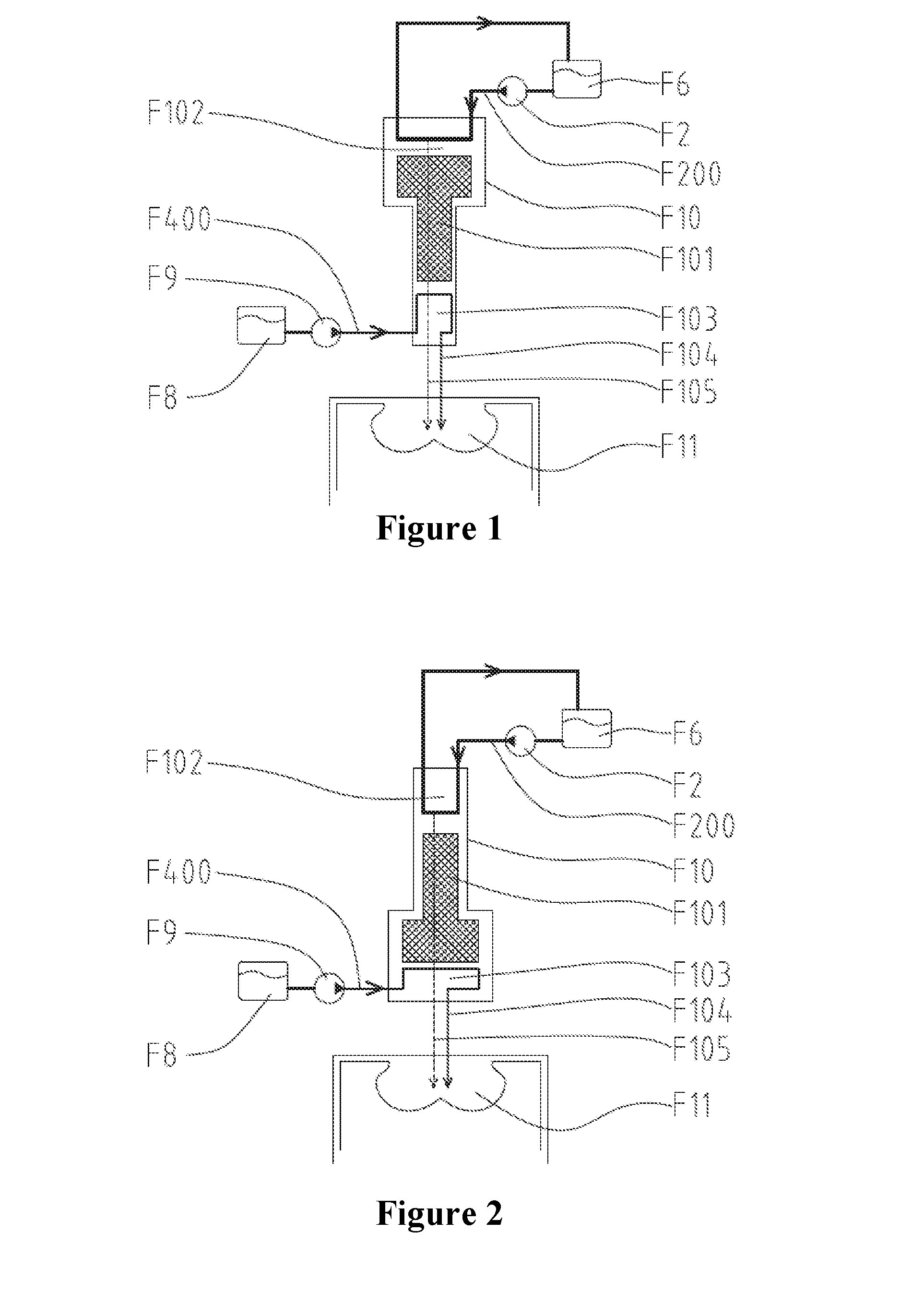
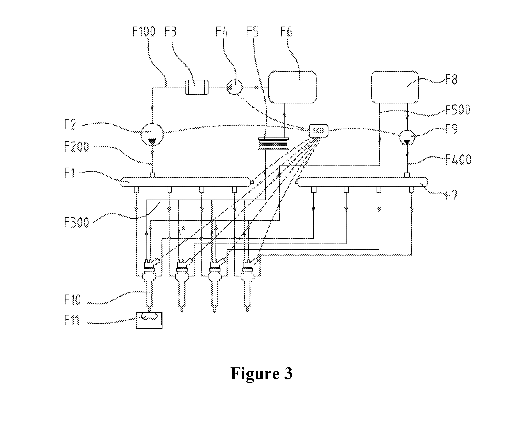
[0046]Referring to FIG. 1, the high pressure loop (F200) deliver a fuel having higher viscosity such as diesel fuel (F6) using a high pressure pump (F2) to intensify the fuel having low viscosity such as gasoline (F8) delivered from the low pressure pump (F9). The low viscosity fuel has been pressurized by high viscosity fuel within pressure intensification chamber (F103) of a fuel injector (F10), and both low viscosity fuel and high viscosity fuels (F104, F105) are directly injected into engine combustion chamber (F11) through fuel injector (F10). In this specific illustration, fuel with low viscosity has been injected with a higher injection pressure than the high viscosity fuel due to the intensifier design with a larger end facing high viscosity fuel.

[0047]FIG. 2 is same as FIG. 1 except fuel having low viscosity has been injected with a lower injection pressure than the high viscosity fuel due to the intensifier design with a smaller end facing high viscosity fuel.

[0048]Referri...


PUM


Abstract

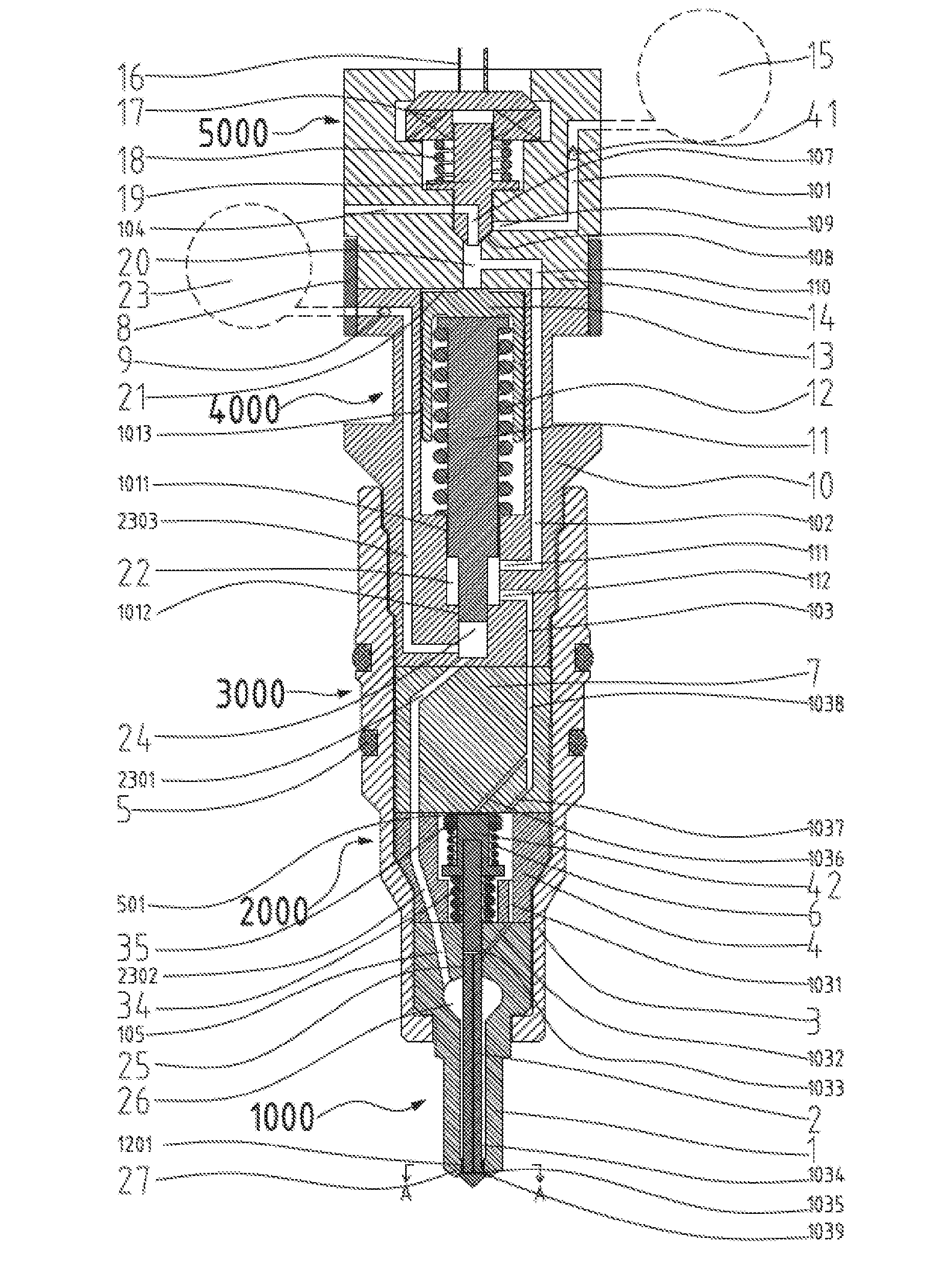
A multi-fuel injector has an internal pressure intensifier which has means to intensify fuels with different viscosities, cetane or octane numbers, with high viscosity fuel being used to intensify itself and low viscosity fuels to high pressure for direct injection into combustion chamber. A fuel injection method and fuel system using such a method of fuel injection is disclosed. A multi-fuel injector with a variable orifice nozzle and variable spray patterns is also disclosed.

Description

CROSS REFERENCE TO RELATED APPLICATION[0001]This application is the National Stage Entry of PCT / US2013 / 044863.TECHNICAL FIELDS[0002]This invention related to a fuel injector, method and system of direct fuel injection for single fuel and multiple fuels, especially for internal combustion engines.BACKGROUND OF THE INVENTIONDescription of the Related Art[0003]The combustion process in a conventional direct injection Diesel engine is characterized by diffusion combustion with a fixed-spray-angle multi-hole fuel injector. Due to its intrinsic non-homogeneous characteristics of fuel-air mixture formation, it is often contradictory to simultaneously reduce soot and NO sub(x)formation in a conventional diesel engine. Progress has been made in recent years for advanced combustion modes, such as Homogeneous-Charge Compression-Ignition (HCCI) combustion and Premixed Charge Compression Ignition (PCCI). However, many issues remain to be solved to control the ignition timing, the duration of com...

Claims


Application Information

Patent Timeline
Patent Type & Authority Applications(United States)
IPC IPC(8): F02M43/04F02M61/10F02M61/18F02M25/03F02M51/06
CPCF02M43/04F02M25/03F02M61/10F02M61/18F02M51/06F02D19/0694F02M45/086F02M47/027F02M57/025Y02T10/30
Inventor HOU, DEYANG
Owner QUANTLOGIC CORP
Learn More