Method of operating electric arc furnace

a technology of electric arc furnace and electric arc furnace, which is applied in the direction of furnaces, charge manipulation, lighting and heating apparatus, etc., can solve the problems of uniform melting of metal materials, relatively weak heating by electrodes at the cold spots, and easy melting of metal materials at the hot spots, so as to improve melting efficiency and speed of melting speed , the effect of reducing the number of operations

Active Publication Date: 2016-05-05
DAIDO STEEL CO LTD
View PDF4 Cites 7 Cited by
  • Summary
  • Abstract
  • Description
  • Claims
  • Application Information

AI Technical Summary

Benefits of technology

[0060]In the case of using an electric arc furnace further including a burner provided on the furnace roof so as to face downwards in a position between the electrodes which are adjacent to each other in a circumferential direction, after a charging step of charging the metal material into the furnace shell via a charging opening, a melting operation can be performed by carrying out a rotating step of rotating the furnace shell relative to the electrodes and the burners during the melting of the metal material. By performing such a rotating step, since the heating position from the burner for the metal material can be changed in a rotational direction, the metal material over a wide range in the circumferential direction can be heated by the burner, and heating by the burners can be made more uniform. Accordingly, the metal material can be more uniformly melted, the speed of melting can be increased, and a melting operation can be shortened.
[0061]According to the present invention as described above, in an operation of an electric arc furnace in which a metal material is melted, unmelted residue can be effectively prevented from being formed in the vicinity of, in particular, a tapping hole or a slag door, and melting efficiency can be improved. Further, more uniform and high-speed melting can be achieved.

Problems solved by technology

In the melting operation of a metal material using such an electric arc furnace, conventionally, there arises a problem of ununiform melting of the metal material.
The metal material at the hot spots is easily melted since the metal material at the hot spots is strongly heated by the electrodes, but the heating by the electrodes is relatively weak at the cold spots.
This causes ununiform melting that the metal material at the cold spots remains unmelted even after the metal material at the hot spots is completely melted.
Due to such a ununiform melting, there arise some problems.
One problem is, for example, that melting efficiency is worse and the cost for electricity required for melting goes up.
Another problem is, for example, that even after the metal material at the hot spots is completely melted, powerful heat is continuously applied during the metal material at the cold spots is continuously being melted, and thus investment of excessive electricity is necessary, melt-erosion of a refractory material of a furnace wall accelerates, and a melt-eroded portion of the refractory material has to be repaired in short cycles.
Therefore, it is difficult to satisfactorily melt the metal material, which has remained unmelted around the tapping hole or the slag door, by the operation merely switching the hot spot and the cold spot by means of relative rotation between the furnace shell and the electrodes.
Naturally, in the operation of an electric arc furnace which does not perform the switching between hot spots and cold spots by a rotation using a rotating apparatus, it becomes more difficult to satisfactorily melt the metal material which has remained unmelted around a tapping hole or a slag door.
For this reason, the heating of the remaining metal material M by the burner 106 becomes weak rapidly, and thus, heating efficiency by the burner 106 for the material at the cold spot is worse, the melting time in the electric arc furnace is prolonged, and a large amount of heating energy is required, and thus, there arises a problem that the total costs go up.
It is possible to expand a heating range by increasing the number of burners; however, in this case, energy cost becomes worse, and thus it has been deemed to be not practical.

Method used


Image

  • Method of operating electric arc furnace
  • Method of operating electric arc furnace
  • Method of operating electric arc furnace

Examples


Embodiment Construction

[0079]Hereinafter, embodiments in which the present invention is applied to an electric arc furnace melting a metal material (herein, steel material) will be described in detail with reference to the drawings.

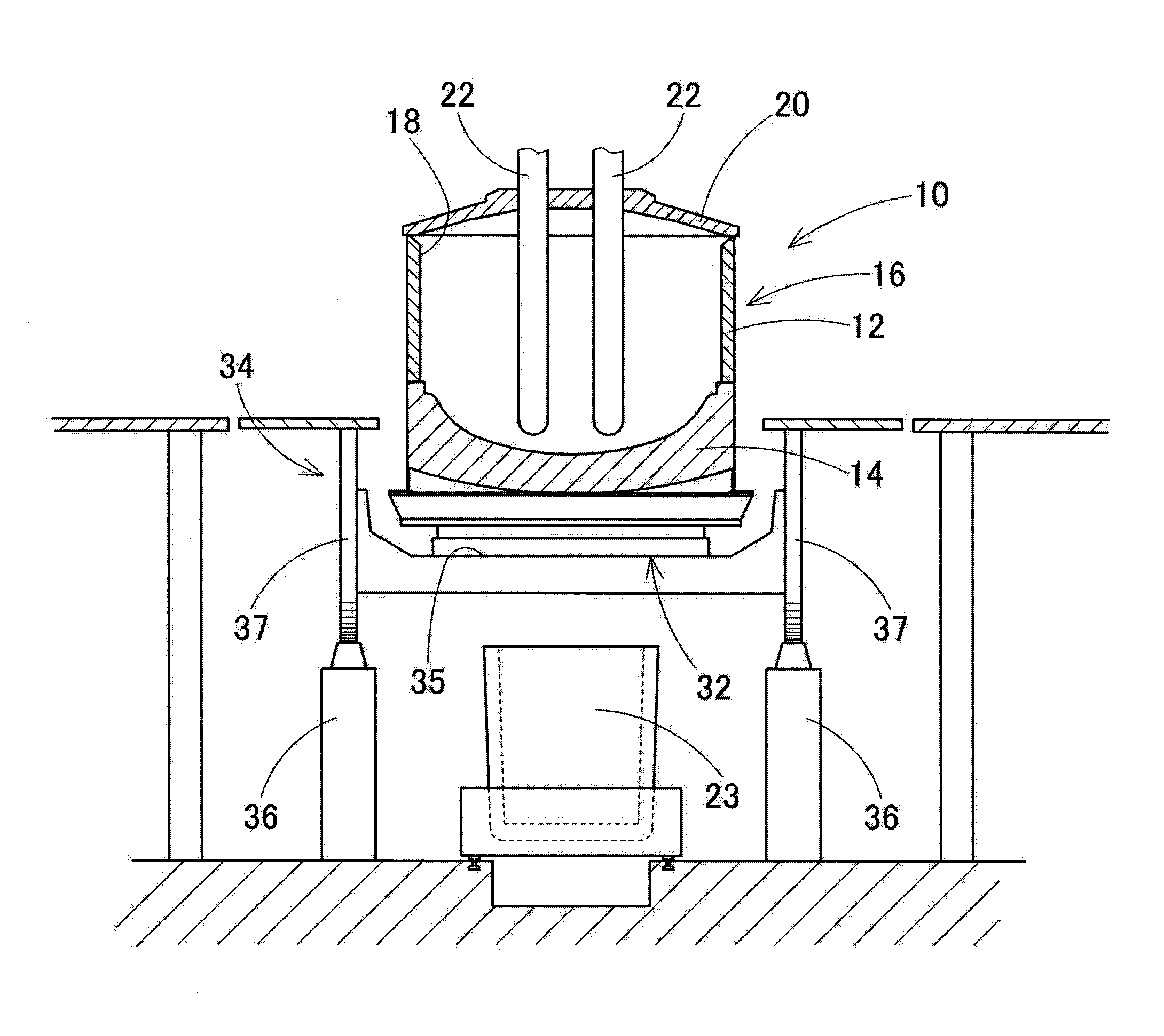
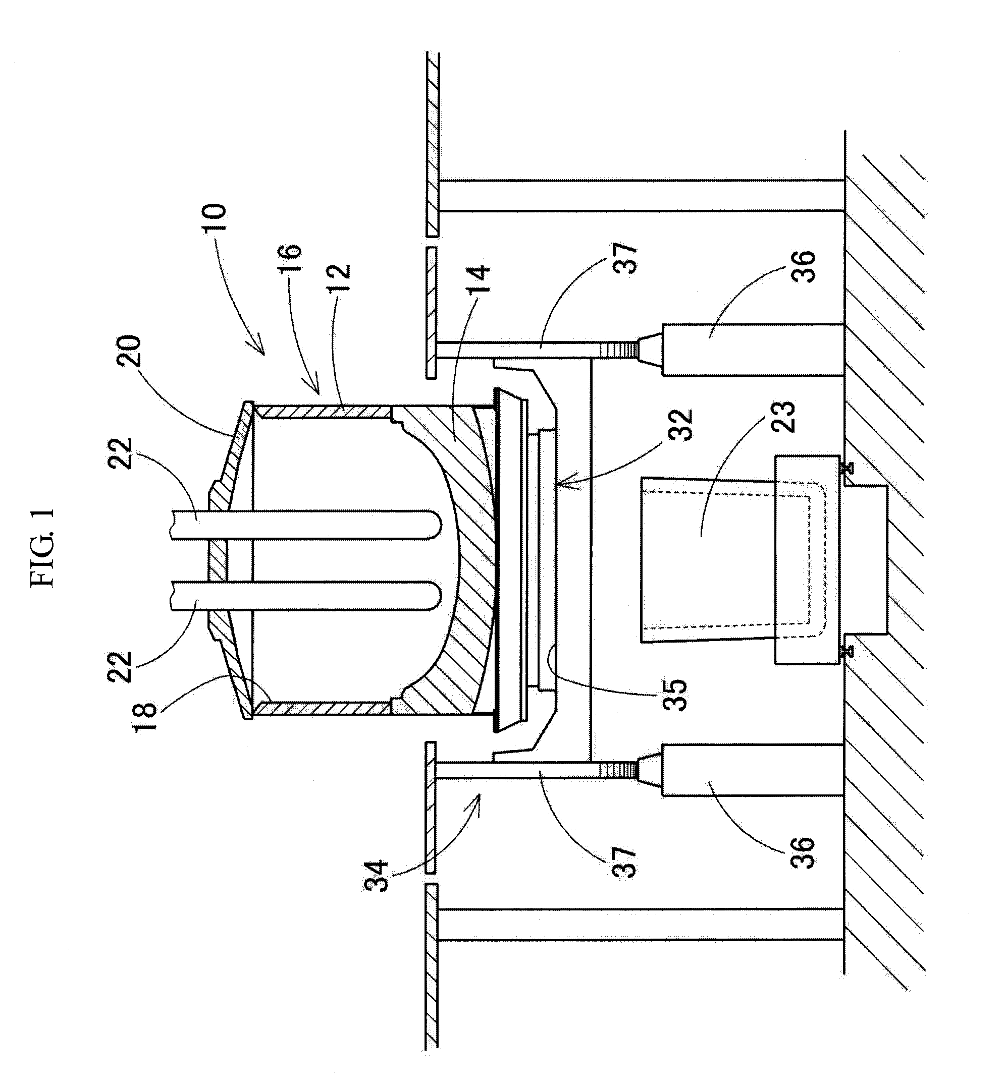
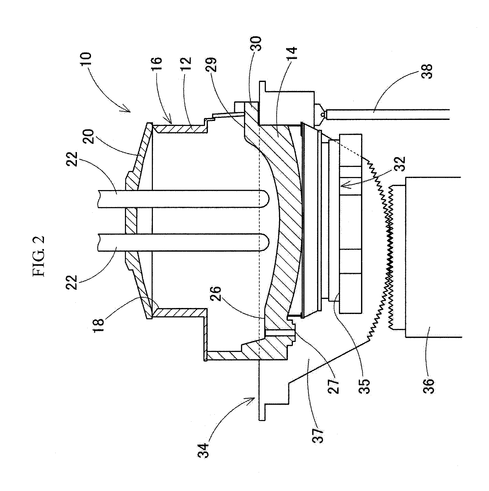
[0080]FIG. 1 and FIG. 2 are views illustrating a configuration of the electric arc furnace that is used in an operation method in the present embodiment.

[0081]In FIG. 1, a reference numeral 10 represents an electric arc furnace, which includes a furnace shell 16 that includes a cylindrical (herein, circular cylindrical) circumferential wall portion 12, a furnace bottom portion 14 and a charging opening 18; a furnace roof 20 that openably and closably shuts the charging opening 18 at an upper end of the furnace shell 16; and three electrodes 22 which are inserted downwards into the furnace shell 16 while passing through the furnace roof 20.

[0082]Each of the electrodes 22 is disposed close to the center of the furnace roof 20 with a substantially circular shape in a plan view, wh...


PUM

PropertyMeasurementUnit
angleaaaaaaaaaa
angleaaaaaaaaaa
angleaaaaaaaaaa

Abstract

The present invention relates to a method of operating an electric arc furnace containing (a) a furnace shell having a tapping hole and/or a slag door, (b) a furnace roof having a plurality of electrodes provided so as to face downwards, and (c) a rotating apparatus that rotates the furnace shell around a vertical axis relative to the electrodes, the method contains a rotating step of rotating the furnace shell relative to the electrodes during melting of a metal material, and a holding step of stopping the rotation when any one of the plurality of electrodes reaches a holding position that is previously set close to the tapping hole or the slag door, and holding the furnace shell at the holding position.

Description

FIELD OF THE INVENTION[0001]The present invention relates to a method of operating an electric arc furnace, and specifically, relates to a method of operating an electric arc furnace with a rotating apparatus that rotates a furnace shell relative to an electrode.BACKGROUND ART OF THE INVENTION[0002]Conventionally, a three-phase alternating current arc furnace in which arcs are produced between a metal material in a furnace shell and three electrodes inserted into the furnace shell to melt the metal material by arc heat is widely used as a melting furnace for melting metal materials such as metal scrap.[0003]In the melting operation of a metal material using such an electric arc furnace, conventionally, there arises a problem of ununiform melting of the metal material.[0004]In the three-phase alternating current electric arc furnace, three electrodes inserted downwards into the furnace shell are disposed so as to form a triangle around the central axis of the furnace shell in a plane...

Claims


Application Information

Patent Timeline
Patent Type & Authority Applications(United States)
IPC IPC(8): F27B3/08F27D11/10F27B3/06F27D3/15
CPCF27B3/085F27B3/06F27D11/10F27D3/1518F27B3/205Y02P10/20
Inventor TOMITA, NORIYUKITANAKA, YOSHIKAZUNAGATANI, AKIHIROOGAWA, MASATOMATSUO, KUNIO
Owner DAIDO STEEL CO LTD
Why Eureka
Try Eureka