Depth measurement apparatus, imaging apparatus and depth measurement method

Active Publication Date: 2016-05-05
CANON KK
View PDF7 Cites 14 Cited by
  • Summary
  • Abstract
  • Description
  • Claims
  • Application Information

AI Technical Summary

Benefits of technology

[0015]According to the depth measurement method of the present invention, the de

Problems solved by technology

A similar problem is generated when a brightness image acquired from an imaging device having a Bayer array by YUV conversion.
Further, if a brightness image of a green pixel (G image) in a Bayer array is used, correct depth measurement cannot be performed if the object image does not include a green

Method used


Image

  • Depth measurement apparatus, imaging apparatus and depth measurement method
  • Depth measurement apparatus, imaging apparatus and depth measurement method
  • Depth measurement apparatus, imaging apparatus and depth measurement method

Examples


embodiment 1

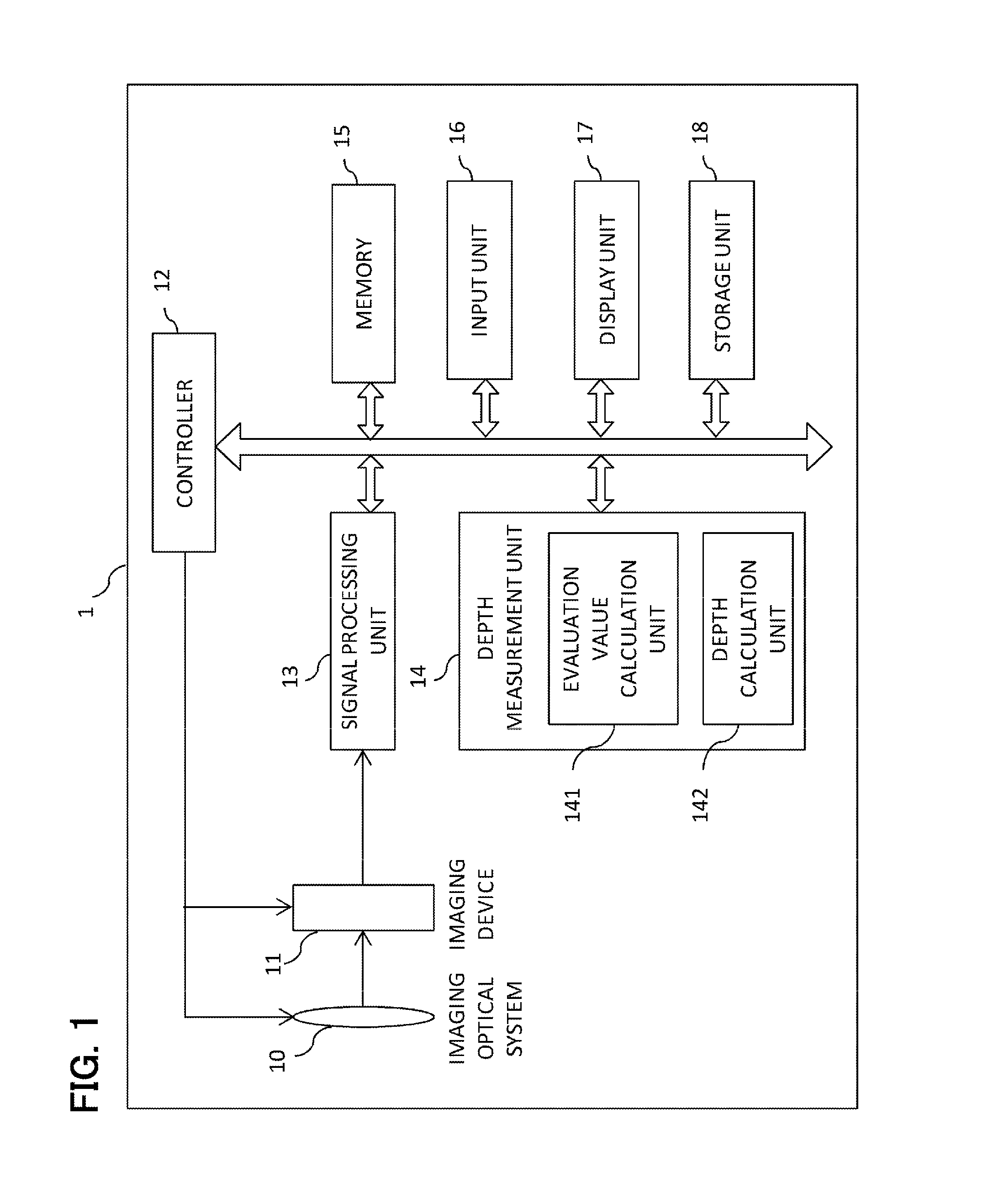
[0027]FIG. 1 is a system block diagram depicting an imaging apparatus according to Embodiment 1 of the present invention. The imaging apparatus 1 has an imaging optical system 10, an imaging device 11, a control unit 12, a signal processing unit 13, a depth measurement unit 14, a memory 15, an input unit 16, a display unit 17 and a storage unit 18.

[0028]The imaging optical system 10 is an optical system that is constituted by a plurality of lenses, and forms an image of incident light on an image plane of the imaging device 11. For the imaging optical system 10, a variable-focus optical system is used, which can automatically focus using an auto focusing function of the control unit 12. The auto focusing method may be a passive type or active type.

[0029]The imaging device 11 is an imaging device having a CCD or CMOS, and acquires a color image. The imaging device 11 may be an imaging device having a color filter, or may be an imaging device having three different colored plates. The...

embodiment 2

[0065]Embodiment 2 of the present invention will be described next. A difference of Embodiment 2 from Embodiment 1 is the method for integrating depth which is calculated for each color plane (S27). The configuration of the imaging apparatus 1 is the same as Embodiment 1, hence same reference symbols are used for description. Primary differences in processing from Embodiment 1 will be described herein below. FIG. 6 is a flow chart depicting the flow in the depth integration step S27 in Embodiment 2.

[0066]The evaluation value calculation step S31 is the same as Embodiment 1. Various values described in Embodiment 1 can be used for the evaluation value. A case when the brightness value for each color plane before correcting the transmittance of the color filter is used for the evaluation value will be described herein below.

[0067]In this embodiment, the depth in the target pixel is not determined as the depth calculated from one color plane, but is determined as the weighted average v...

embodiment 3

[0074]Embodiment 3 of the present invention will now be described. A difference of Embodiment 3 from Embodiment 1 and Embodiment 2 is that the correlation values determined during the depth calculation are considered in the method for integrating the calculated depth values for each color plane (S27). The configuration of the imaging apparatus 1 in Embodiment 3 is the same as Embodiment 1 and Embodiment 2, therefore the same reference symbols are used for description. Primary differences of the processing from Embodiment 1 and Embodiment 2 will be described herein below.

[0075]FIG. 7A and FIG. 7B are flow charts depicting the flow of the depth integration step S27 in this embodiment. FIG. 7A shows an example of processing based on Embodiment 1, and FIG. 7B shows an example of processing based on Embodiment 2.

[0076]In this embodiment, the depth information of a color plane having a high correlation value, when the depth is calculated for each color plane (see step S24 in FIG. 3, Expre...


PUM


Abstract

A depth measurement apparatus that calculates depth information of an object based on a first color image and a second color image, includes: a depth calculator adapted to calculate depth information of a target pixel in a color plane, using the two color images; and an evaluator adapted to calculate, for each color plane, an evaluation value to indicate a confidence coefficient of the depth information in the target pixel, wherein the depth calculator is further adapted to determine, based on the evaluation value, a color plane from which the depth information of the target pixel is calculated.

Description

BACKGROUND OF THE INVENTION[0001]1. Field of the Invention[0002]The present invention relates to a depth measurement apparatus.[0003]2. Description of the Related Art[0004]As a technique to acquire a depth of a photographed scene from an image acquired by an imaging apparatus, the Depth from Defocus (DFD) method as disclosed in Patent Literature 1 (Japanese Patent Application Laid-Open No. 2010-016743) has been proposed. In the DFD method, a plurality of images having different degrees of blur is acquired by controlling the photographing parameters of an imaging optical system, and in the plurality of acquired images, the degree of blur and correlation amount are calculated using the measurement target pixel and peripheral pixels thereof. The degree of blur and correlation amount change according to the depth of an object in the image, therefore the depth is calculated using these relationships. The depth measurement by the DFD method can be incorporated into a commercially availabl...

Claims


Application Information

Patent Timeline
IPC IPC(8): G06T7/00G01B11/22G06K9/62G06K9/52G06T7/40G06K9/46G06V10/56G06V10/143
CPCG06T7/0065G06T7/408G06K9/4652G06T2207/20212G06K9/6202G06K9/52G01B11/22G06K9/4661G06T2207/10024G06T7/521G06T7/571G06V20/647G06V10/143G06V10/56G06V10/803G06F18/251G06T7/55
Inventor KOMATSU, SATORU
Owner CANON KK
Why Eureka
Try Eureka