Filter assembly and method

a filter assembly and filter technology, applied in the field of electronic filter assemblies, can solve the problems of reducing the service life or damage of the filter assembly, the filter assembly may be large and heavy, and the type of the filter assembly may not be magnetically symmetri

Active Publication Date: 2016-05-05
GE GLOBAL SOURCING LLC
View PDF9 Cites 43 Cited by
  • Summary
  • Abstract
  • Description
  • Claims
  • Application Information

AI Technical Summary

Problems solved by technology

Due to the vertical orientation of the limbs, these types of filter assemblies may not be magnetically symmetric.
This can cause an uneven temperature or heating distribution in the limbs and yokes, which may lead to decreased service life or damage to the filter assemblies.
Additionally, because the yokes typically are relatively large in order to be coupled with the limbs, the filter assemblies may be large and heavy.
The asymmetric filter assemblies also can ca

Method used


Image

  • Filter assembly and method
  • Filter assembly and method
  • Filter assembly and method

Examples


Embodiment Construction

[0020]One or more embodiments of the assemblies and methods described herein provide symmetric common-mode structures for filter assemblies, such as for filters used in power-electronics inverters. The assemblies described herein can be relatively easy to manufacture and can provide compact, light-weight, and / or lower cost filters relative to some known core-type filters.

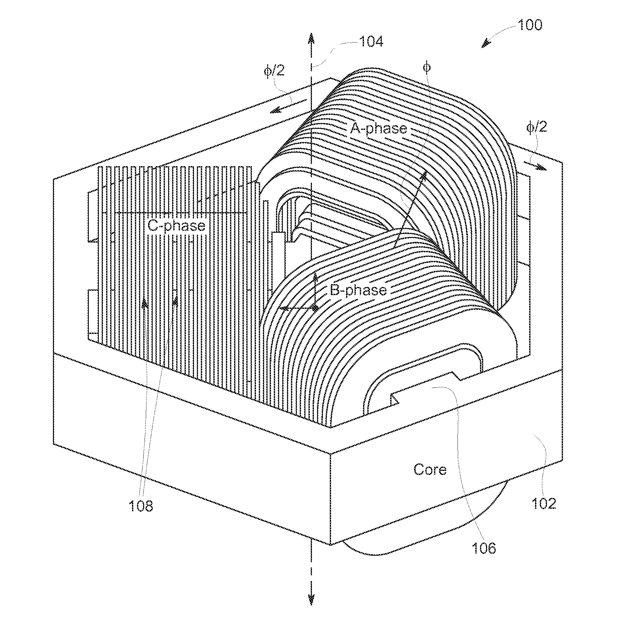
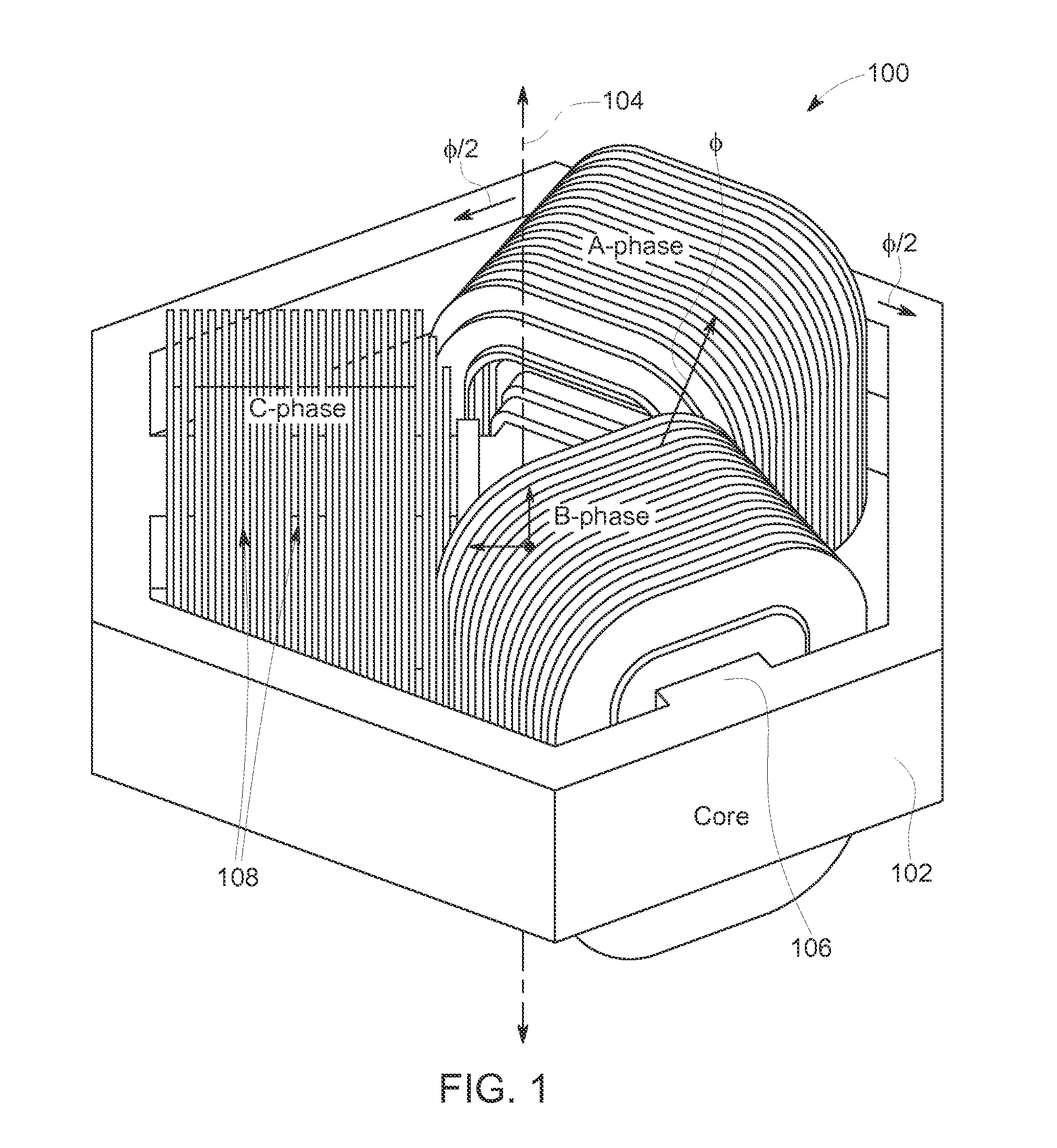
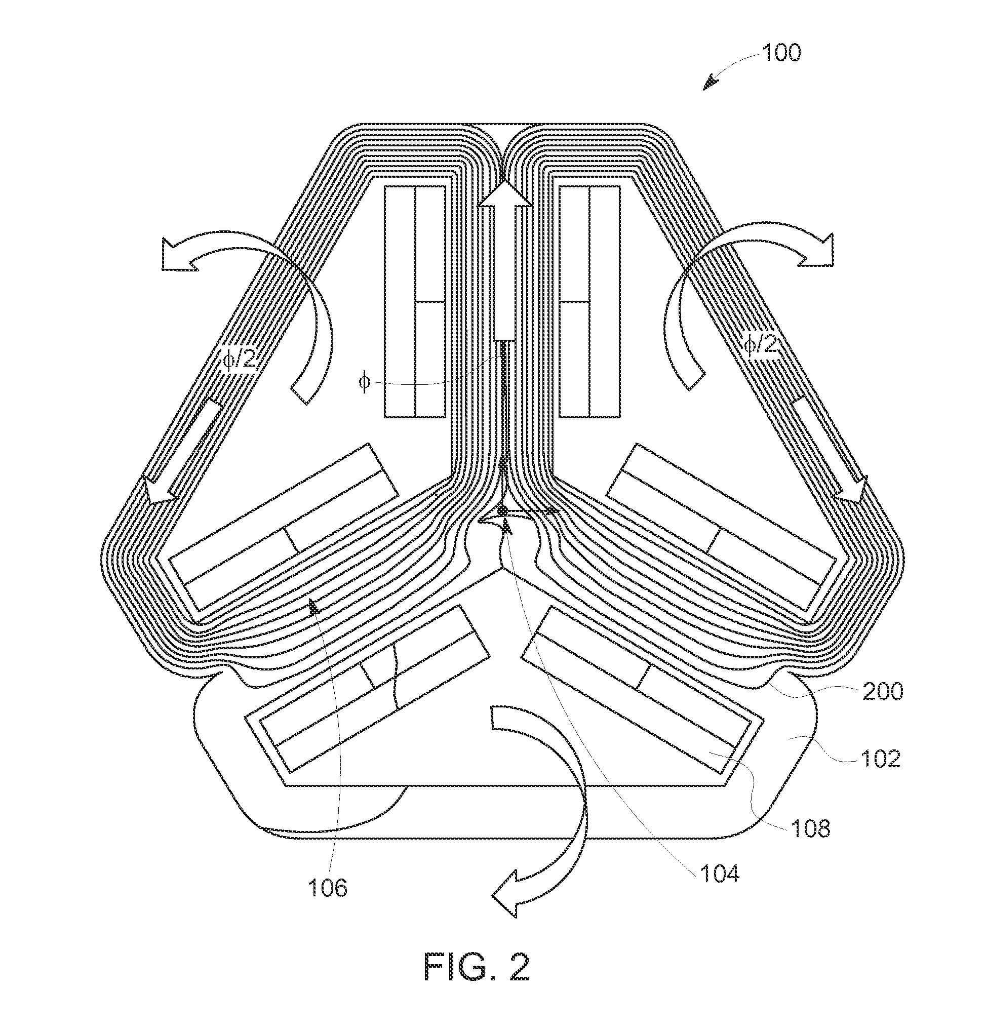
[0021]FIG. 1 is a perspective view of a symmetric filter assembly 100 according to one embodiment. FIG. 2 is a schematic diagram of the filter assembly 100 shown in FIG. 1. FIG. 2 illustrates the flow of magnetic flux through the filter assembly 100. The filter assembly 100 includes an annular yoke or core body 102 that extends around (e.g., encircles) a center axis 104. The core body 102 may have a non-circular shape as shown in FIG. 1, may have a circular shape, or may have another shape. The core body 102 can be formed from a magnetically conductive material, such as a ferrite material. The filter assembly 100 al...


PUM


Abstract

An electronic filter assembly includes a magnetically conductive annular body extending around a center axis, a set of magnetically conductive prongs radially extending from the center axis toward the annular body, and conductive windings extending around the prongs. The conductive windings can be disposed around the prongs instead of the annular body to assist in conduction of common mode magnetic flux, to reduce impedance of the filter assembly, and/or to more evenly distribute temperature in the filter assembly. A method for forming an electronic filter assembly includes forming an electronic filter assembly having a magnetically conductive annular body extending around a center axis and a set of magnetically conductive prongs radially extending from the center axis toward the annular body. The annular body and the prongs can be formed by coupling plural layers of magnetically conductive bodies together.

Description

CROSS-REFERENCE TO RELATED APPLICATIONS[0001]This application claims priority to U.S. Provisional Application No. 62 / 069,946, which was filed on 29 Oct. 2014, and the entire disclosure of which is incorporated by reference.FIELD[0002]Embodiments of the subject matter disclosed herein relate to electronic filter assemblies, such as inverters, transformers, or the like.BACKGROUND[0003]Some electronic filter assemblies used for multi-phase electric currents include transformers, inductors, and the like. These assemblies can include vertically oriented and parallel ferrite limbs joined by horizontally oriented and parallel ferrite yokes. Conductive wires are wound around the vertical limbs to form the assemblies. During operation, electric current is conducted by some of these windings to induce magnetic flux in the ferrite limbs and yokes. This flux can be conducted through the yokes to other limbs, where the flux can induce another current in the wires. This other current can be a cur...

Claims


Application Information

Patent Timeline
IPC IPC(8): H01F27/24H01F41/02
CPCH01F41/0206H01F27/24H01F37/00H01F27/263H01F27/28H01F41/0233
Inventor BHIDE, RAVINDRA SHYAMKUMAR, AJITH KUTTANNAIRDURANTAY, LIONELRALLABANDI, VANDANA
Owner GE GLOBAL SOURCING LLC
Why Eureka
Try Eureka