
High-Power Microwave Beam Steerable Array and Related Methods

a beam steerable array and high-power microwave technology, applied in the direction of instruments, antennas, communication jamming, etc., can solve the problems of limited mission planning ability, impracticality of hpm source size, and limited number of elements which can be used in a given system, so as to increase the number of high-power microwave pulses

Active Publication Date: 2016-05-05
BAE SYST INFORMATION & ELECTRONICS SYST INTERGRATION INC
View PDF3 Cites 10 Cited by
  • Summary
  • Abstract
  • Description
  • Claims
  • Application Information

AI Technical Summary

Benefits of technology

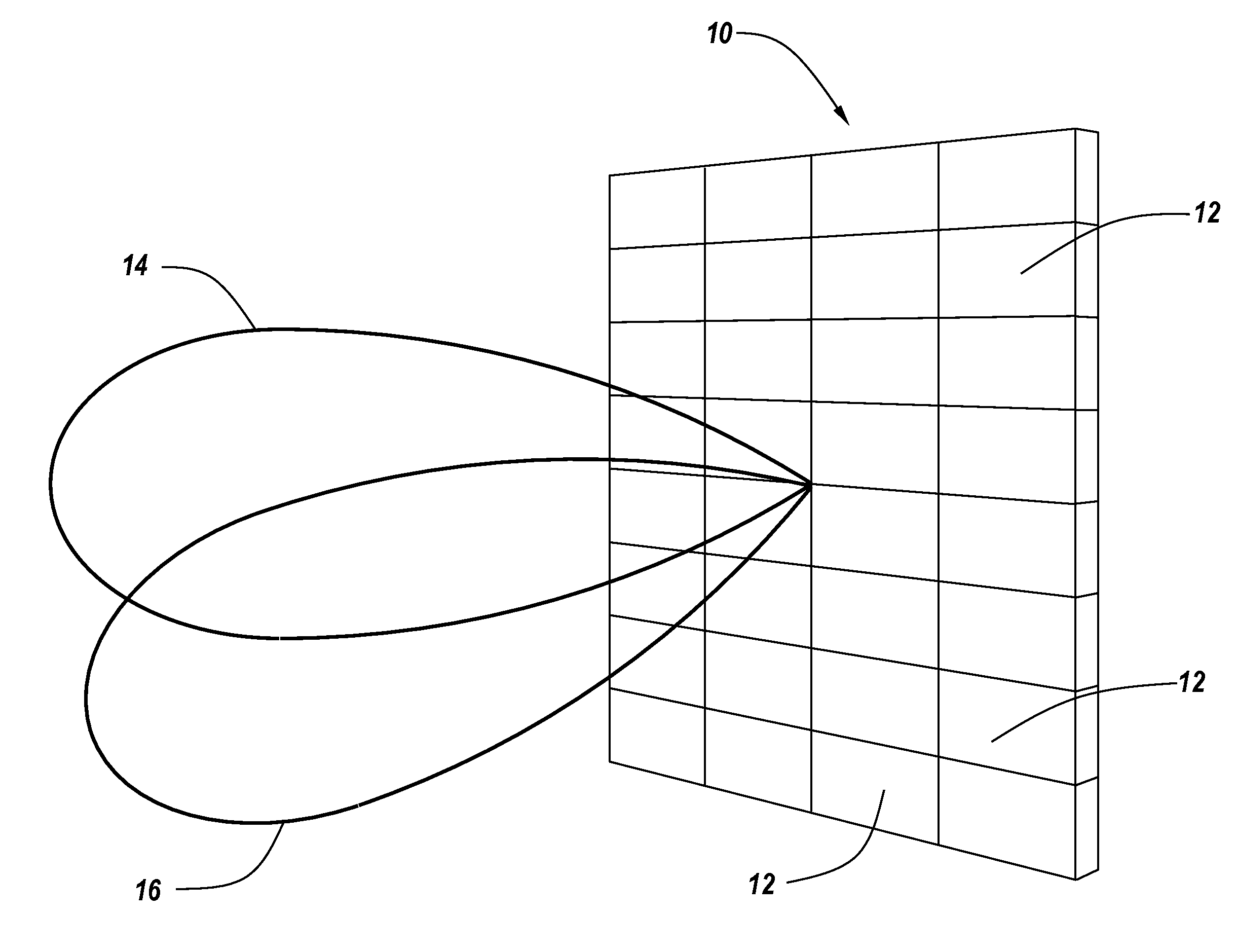
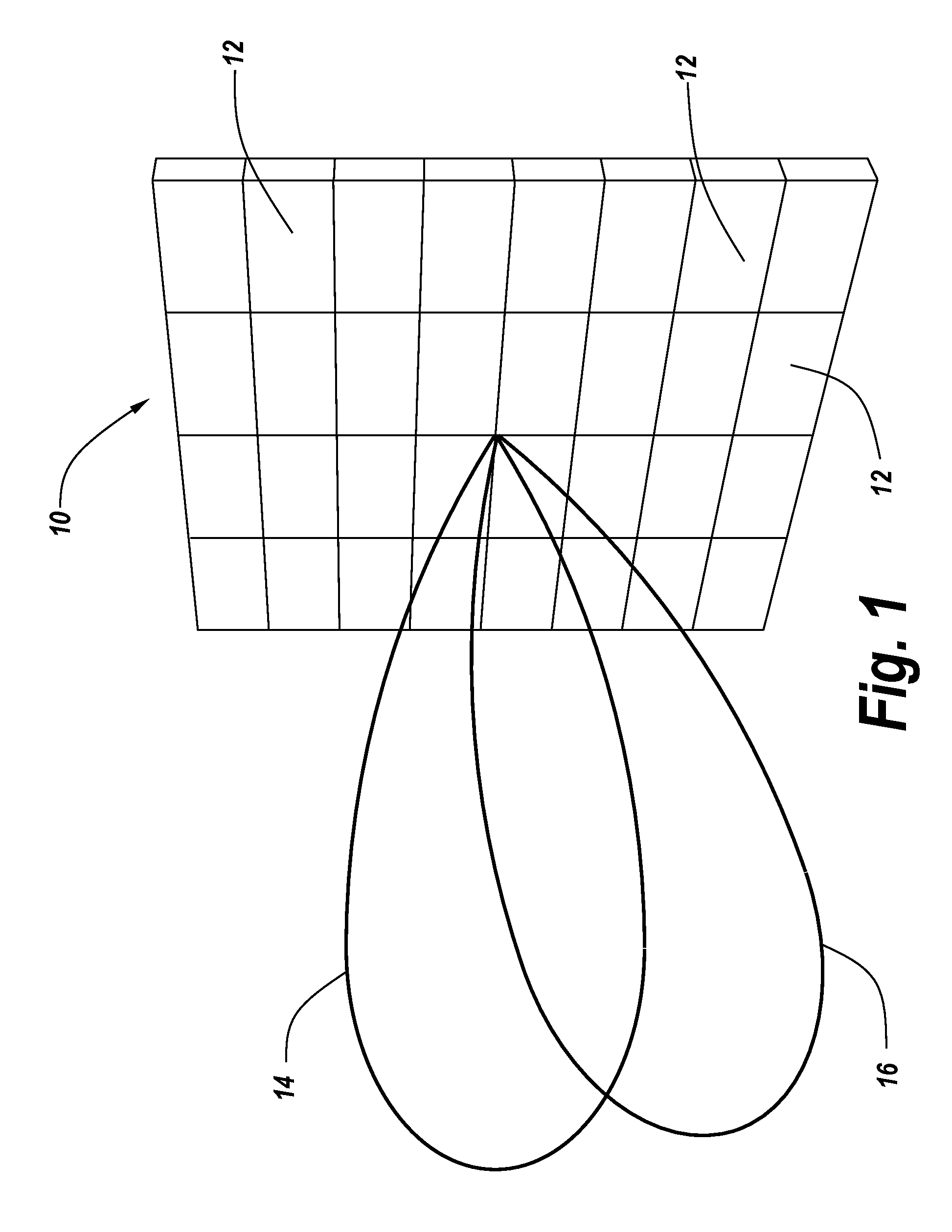
The present disclosure provides a way to illuminate a target with powerful microwave pulses from a moving vehicle. This system generates high power microwave pulses using a microwave radar and sends them in a beam directed towards the target. As the vehicle moves, the beam tracks the target and increases the number of high power pulses that impinge upon it. This provides a way to increase the effectiveness and accuracy of microwave radar.

Problems solved by technology

However, platform constraints typically make the increase of the HPM source size impractical, thereby limiting the number of elements which can be used in a given system.
Thus, the ability to do mission planning is limited because of the fixed positioning of the antenna, where pointing the antenna is dependent upon the orientation of the platform.
Another problem with HPM systems is the present pointing accuracy.
Conventional pulsed HPM systems do not have accurate timing control and do not have an easy or straightforward solution for beam steering.
However, if the antennas are only pointing in one direction because they are fixed to the platform, the time at which the pulses can be turned on and off can be significantly limited.
Similarly, if it is desirable to strafe a target with multiple high-energy pulses, it can only be done when the vehicle with its antenna is directly aiming at the target.
As a result, as the vehicle passes by the target, firing can only commence once the target is immediately in the aim of the antenna.
The problem, however, is how to be able to project high-energy pulses towards a target in a steerable manner.
However, it is not at all clear how to phase ultra-short high-power pulses.
Moreover, it is likewise not clear how to calculate the phase of ultra-short pulses projected by multiple antennas where there is no necessary instantaneous phase relationship between these pulses.
While it is possible in conventional phased array radars to ascertain the phase relationship between continuous waves, it is not entirely clear how one could adapt phased array technology to provide beam steering for high-energy pulsed systems.
Although the concept of phased array beam steering is well developed for continuous wave low power sources, conventional pulsed HPM systems do not have accurate timing control, and thus do not have an easy or straight forward solution for beam steering.
Furthermore, the possibility of constructive interference of short pulses within a wide steering angle has been thought to be questionable at best.
Additionally, the idea of using a large number of very small elements stacked together in an array and to control the timing of the projection of the pulses at each of these elements to get a beam steering effect has not been possible due to the fact that, when dealing with individual pulses, it had not been proven that one could effectively time the leading edges of these pulses with highly precise phase delays to provide the appropriate beam steering characteristic.
Thus, a heretofore unaddressed need exists in the industry to address the aforementioned deficiencies and inadequacies.

Method used


Image

  • High-Power Microwave Beam Steerable Array and Related Methods
  • High-Power Microwave Beam Steerable Array and Related Methods
  • High-Power Microwave Beam Steerable Array and Related Methods

Examples


Embodiment Construction

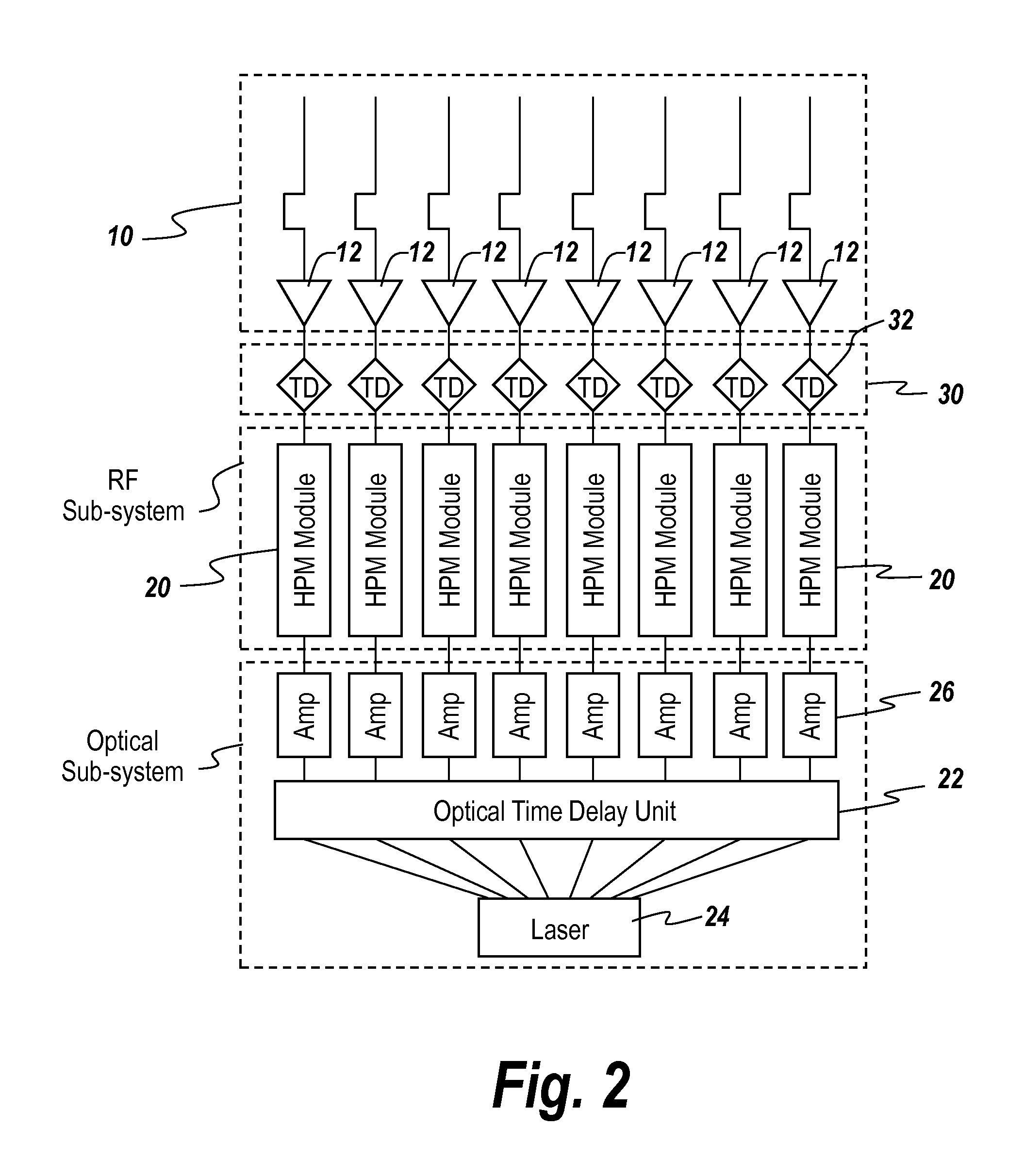
[0025]To improve on the shortcomings of the conventional art, and provide steerability to high-power pulses coming from an array, the subject invention involves pulse generation timing including an optical time delay or RF time delay, or both. As to optical time delay, modules having laser controlled photoconductive switches may be used. As to RF time delay, delay controllable transmission lines may be used. In each case, pulses emanating from the array elements may have the requisite phase delay for beam steering. As will be seen below, the two delay systems can be used independently or together.

[0026]In the present disclosure, there may be two different types of mechanisms to control the timing of the pulses that are emitted. The two mechanisms to control the timing of the leading edges of these pulses involves either (1) the use of an optical delay line, so that the pulses to each of the modules in the array are precisely delayed with respect to each other to provide the beam ste...


PUM


Abstract

A steerable high-power microwave beam array includes an optical sub-system comprising a laser and an optical time delay unit and a parallel set of RF time delay units. The optical system and / or the RF delay subsystem are utilized to precisely delay the pulses from the microwave antenna elements to provide steerable beam forming.

Description

CROSS REFERENCE TO RELATED APPLICATION[0001]This application claims benefit of U.S. Provisional Application Ser. No. 62 / 072,583 entitled, “HIGH POWER MICROWAVE BEAM STEERABLE ARRAY” filed Oct. 30, 2014 the entire disclosure of which is incorporated herein by reference.FIELD OF THE INVENTION[0002]This invention relates to directed-energy weapons, and more particularly, to high-power microwave arrays that produce high-energy pulses on target.BACKGROUND OF THE INVENTION[0003]The conventional solution for increasing high-power microwave (HPM) power is making the source bigger, including increasing the number of modules, and making antennas bigger. However, platform constraints typically make the increase of the HPM source size impractical, thereby limiting the number of elements which can be used in a given system.[0004]More particularly, with high-power microwaves, in order to improve the amount of energy on target a number of antennas are carried on a moving platform such as an aircra...

Claims


Application Information

Patent Timeline
Patent Type & Authority Applications(United States)
IPC IPC(8): H01Q3/26
CPCH01Q3/2676H01Q3/2682
Inventor MCGEEHAN, JOHN E.MOREL, YANNICK C.KOZYREV, ALEXANDER B.LONDON, SIMON Y.NOVOTNY, CLINT J.SENGUPTA, SOMNATHSHEU, YEUAN-MINGWALTER, MARK T.
Owner BAE SYST INFORMATION & ELECTRONICS SYST INTERGRATION INC
Learn More