Two-stage adiabatically coupled photonic systems

a photonic system and adiabatically coupled technology, applied in the direction of instruments, optical waveguide light guides, optical light guides, etc., can solve the problems of many surface grating couplers being highly wavelength dependent, and manufacturers may be unable or unwilling to test such a process

Active Publication Date: 2016-05-12
II VI DELAWARE INC
View PDF0 Cites 84 Cited by
  • Summary
  • Abstract
  • Description
  • Claims
  • Application Information

AI Technical Summary

Benefits of technology

[0007]This Summary is provided to introduce a selection of concepts in a simplified form that are further described below in the Detailed Description. This Summary is not intended

Problems solved by technology

However, many surface grating couplers are highly wavelength dependent and may have a relatively small pass band.
However, the edge co

Method used


Image

  • Two-stage adiabatically coupled photonic systems
  • Two-stage adiabatically coupled photonic systems
  • Two-stage adiabatically coupled photonic systems

Examples


Embodiment Construction

[0007]This Summary is provided to introduce a selection of concepts in a simplified form that are further described below in the Detailed Description. This Summary is not intended to identify key features or essential characteristics of the claimed subject matter, nor is it intended to be used as an aid in determining the scope of the claimed subject matter.

[0008]Some example embodiments described herein generally relate to two-stage adiabatically coupled photonic systems.

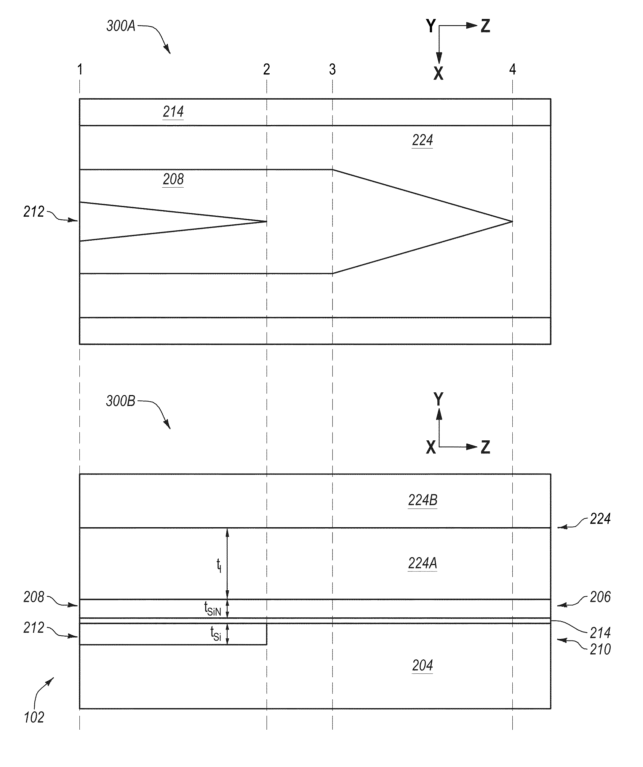
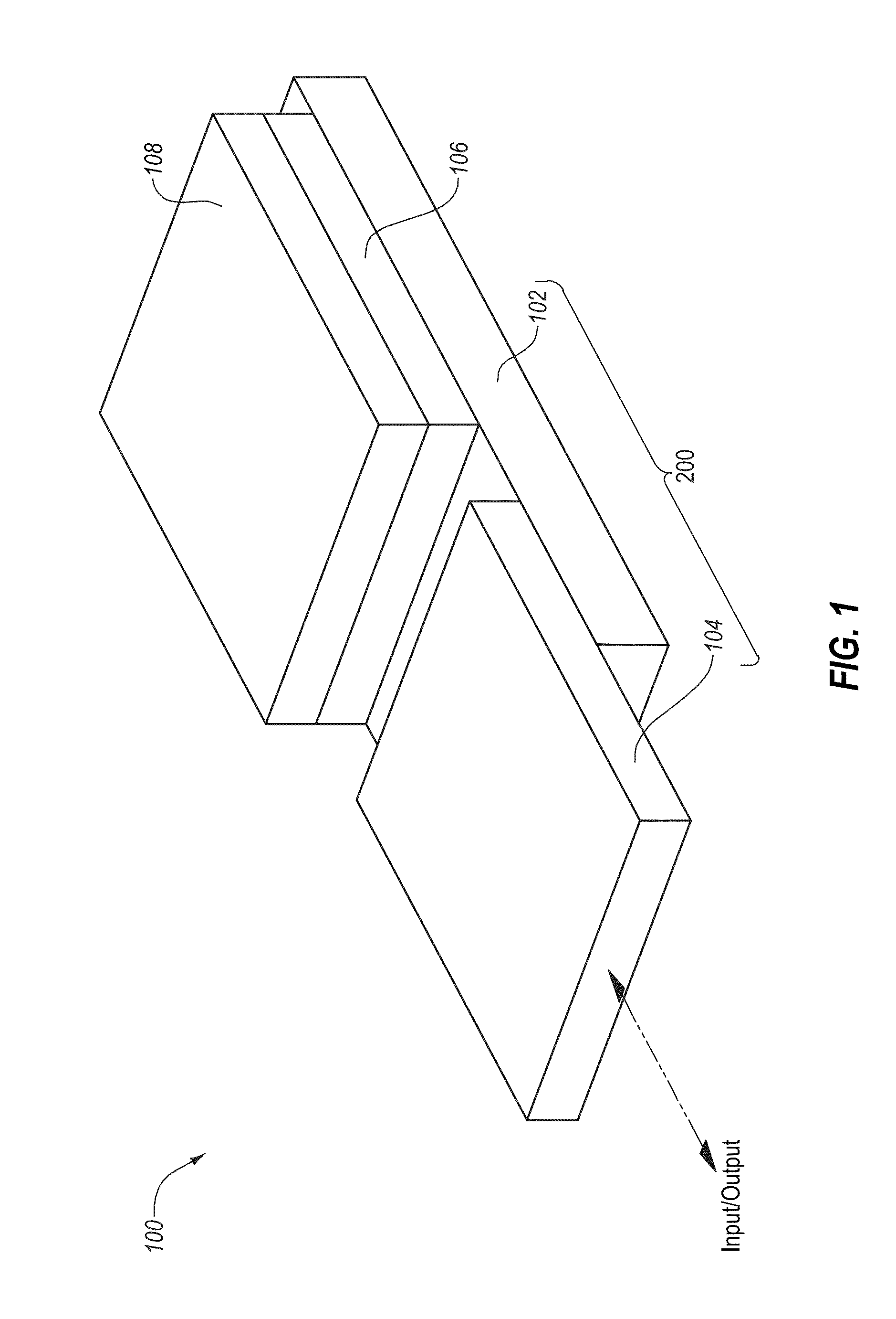
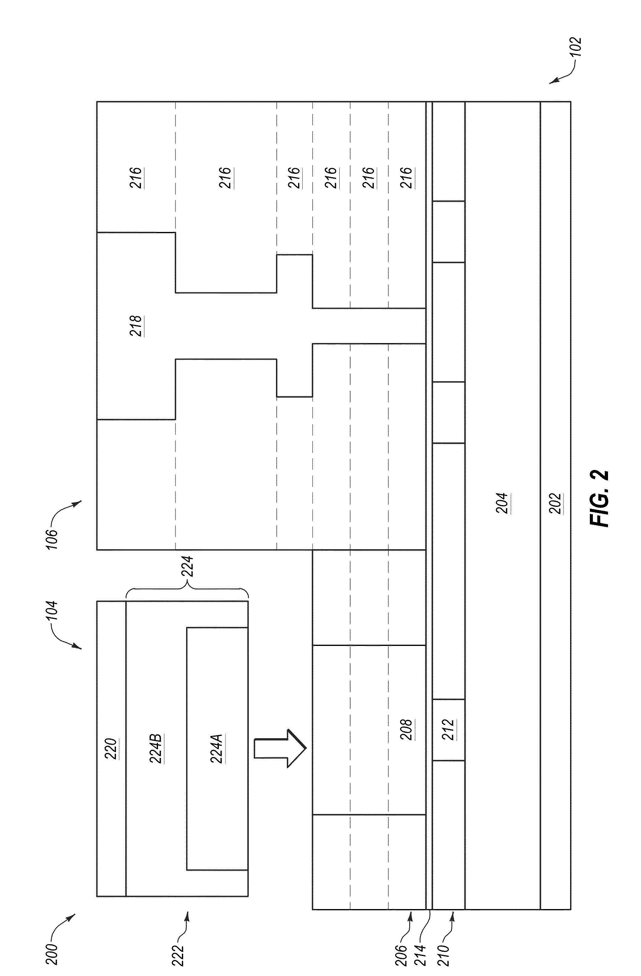
[0009]In an example embodiment, a coupled system may include a first waveguide, at least one second waveguide, and an interposer. The first waveguide may have a first refractive index n1 and a tapered end. The at least one second waveguide may each have a second refractive index n2. The interposer may include a third waveguide having a third refractive index n3 and a coupler portion. The tapered end of the first waveguide may be adiabatically coupled to a coupler portion of one of the at least one second waveguide....


PUM


Abstract

In an example, a coupled system includes a first waveguide, at least one second waveguide, and an interposer. The first waveguide has a first refractive index n1 and a tapered end. The at least one second waveguide each has a second refractive index n2. The interposer includes a third waveguide having a third refractive index n3 and a coupler portion, where n1>n2>n3. The tapered end of the first waveguide is adiabatically coupled to a coupler portion of one of the at least one second waveguide. A tapered end of one of the at least one second waveguide is adiabatically coupled to the coupler portion of the third waveguide of the interposer. The coupled system is configured to adiabatically couple light between the first waveguide and the at least one second waveguide and between the at least one second waveguide and the third waveguide.

Description

CROSS-REFERENCE TO RELATED APPLICATIONS[0001]The present application claims the benefit of and priority to U.S. Provisional Patent Application No. 62 / 078,259, filed on Nov. 11, 2014, U.S. Provisional Patent Application No. 62 / 120,194, filed on Feb. 24, 2015, U.S. Provisional Patent Application No. 62 / 181,679, filed on Jun. 18, 2015, and U.S. Provisional Patent Application No. 62 / 238,542, filed on Oct. 7, 2015. The foregoing applications are incorporated herein by reference.FIELD[0002]The embodiments discussed herein are related to two-stage adiabatically coupled photonic systems.BACKGROUND[0003]Unless otherwise indicated herein, the materials described herein are not prior art to the claims in the present application and are not admitted to be prior art by inclusion in this section.[0004]There are two common solutions to couple light into or out of a silicon (Si) photonic integrated circuit (PIC). For example, surface grating couplers on the Si PIC can couple light into or out of th...

Claims


Application Information

Patent Timeline
IPC IPC(8): G02B6/122G02B6/32G02B6/42G02B6/12G02B6/136G02B6/30G02B6/14G02B6/293
CPCG02B6/1228G02B6/14G02B6/32G02B6/2938G02B6/12016G02B6/136G02B2006/12123G02B6/423G02B2006/12147G02B2006/12061G02B2006/12069G02B2006/12121G02B2006/12157G02B6/305G02B6/126G02B6/4215G02B2006/12164G02B6/1223G02B6/4208G02B6/2773G02B2006/12097G02B6/125G02B6/274G02B6/29325G02B6/1221G02B6/124G02B6/2726G02B2006/12038
Inventor MAHGEREFTEH, DANIELPARK, BRYANCHEN, JIANXIAOXU, XIAOJIEDENOYER, GILLES P.HUEBNER, BERND
Owner II VI DELAWARE INC
Why Eureka
Try Eureka