Pneumatic pressure detector for a fire alarm system and method of insulating

a technology of pneumatic pressure detector and fire alarm system, which is applied in the direction of signalling system, instruments, contacts, etc., can solve the problems of non-functional pneumatic fire detector, switch and pressure tube stress, and significant drop in setting

Active Publication Date: 2016-05-12
KIDDE TECH
View PDF0 Cites 4 Cited by
  • Summary
  • Abstract
  • Description
  • Claims
  • Application Information

AI Technical Summary

Problems solved by technology

A challenge during the test is to protect the two pressure switches so that they are not exposed to the full heat load of the test.
Switches exposed to too much heat during the test can result in the pressure setting dropping significantly, resulting in the pneumatic fire detector failing to either indicate the fire has been removed or the integrity pressure switch failing to indicate a severed sensing element.
If this happens, the potting material can put excessive stresses on the switches and the pressure tubes attached to the switches as it cools when it is removed from the fire.
These undue stresses may cause some type of failure or leak to occur during the cooling process resulting in a non-functioning pneumatic fire detector.
However, under the full heat

Method used


Image

  • Pneumatic pressure detector for a fire alarm system and method of insulating
  • Pneumatic pressure detector for a fire alarm system and method of insulating

Examples


Embodiment Construction

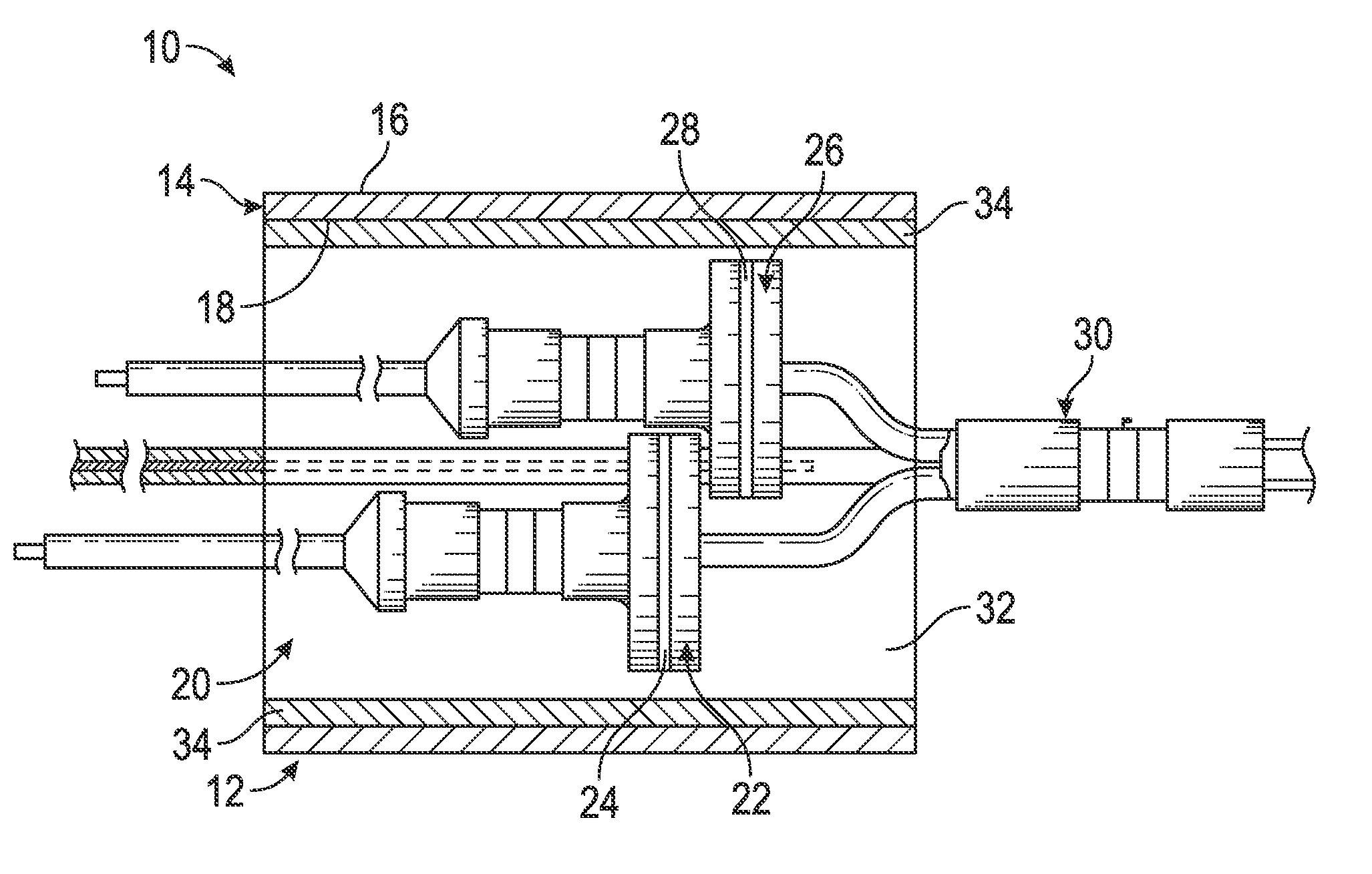
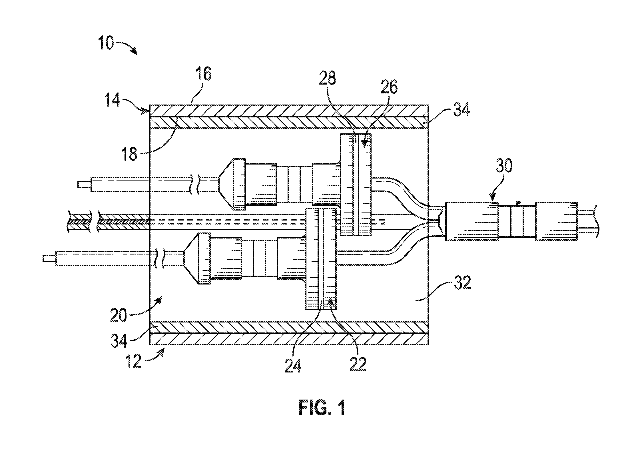
[0012]Referring to FIG. 1, a portion of a fire alarm system 10 is illustrated. Specifically, a pneumatic pressure detector 12 of the fire alarm system 10 is shown. The fire alarm system 10 may be employed in any location that requires the use of an overheat condition, such as that caused by a fire. It is to be appreciated that the fire alarm system 10 may be employed in numerous industries, such as the aerospace industry, where the fire alarm system 10 is disposed on an aircraft.

[0013]The pneumatic pressure detector 12 includes a housing 14 that is constructed out of a metallic material that is capable of conducting an electrical signal. Metallic materials are used so that components disposed therein can maintain their strength when they are subjected to high temperatures. The housing 14 includes an exterior surface 16 and an internal surface 18, with the housing 14 having a substantially cylindrical cross-section in some embodiments. However, alternative cross-sectional geometries ...


PUM


Abstract

A pneumatic pressure detector for a fire alarm system includes a housing having an internal surface defining an interior volume. Also included is an alarm switch located within the interior volume of the housing and comprising a first deformable diaphragm responsive to an increase in pressure of a gas disposed in a sensor tube to indicate an overheat condition. Further included is an integrity switch located within the interior volume and comprising a second deformable diaphragm disposed in contact with an electrical contact during pressurization of the gas within a predetermined pressure range and in an electrically open condition when the pressure of the gas is less than the predetermined range. Yet further included is a mica sleeve located within the interior volume of the housing and disposed along at least a portion of the internal surface of the housing to insulate the alarm switch and the integrity switch.

Description

BACKGROUND OF THE INVENTION[0001]The subject matter disclosed herein relates to fire alarm systems and, more particularly, to a pneumatic pressure detector for a fire alarm system, as well as a method of insulating switches of the pneumatic pressure detector.[0002]Fire alarm systems are employed to detect an overheat condition (e.g., fire) in a wide number of applications in many industries. For example, it is important to detect overheat conditions on aircraft or commercial vehicles. One approach is a pneumatic pressure detector that is part of a system that uses a gas that expands when heated. Upon heating, the gas actuates an associated deformable diaphragm, as well as any other type of switch, to close an electrical switch (e.g., fire alarm switch) to indicate an alarm condition. An integrity switch, or fault switch, also utilizes a deformable diaphragm. The integrity switch is electrically closed under normal operation, but will electrically open if the pneumatic pressure falls...

Claims


Application Information

Patent Timeline
IPC IPC(8): G08B17/04
CPCG08B17/04G08B1/00H01H1/00G08B17/06H01H35/34
Inventor WALLACE, STEVENFRASURE, DAVIDYAMOUSSA, MAHAMADOU
Owner KIDDE TECH
Why Eureka
Try Eureka