High-Frequency Electric Wire, Manufacturing Method Thereof, and Wire Harness

a technology manufacturing method, which is applied in the direction of insulated conductors, cables, conductors, etc., can solve the problems of difficulty in reducing the limiting the finished outer diameter of high-frequency electric wire, and reducing the outer diameter of electric wire. , to achieve the effect of reducing costs, preventing an increase in high-frequency resistance, and reducing the outer diameter of electric wir

Active Publication Date: 2016-05-12
YAZAKI CORP
View PDF7 Cites 9 Cited by
  • Summary
  • Abstract
  • Description
  • Claims
  • Application Information

AI Technical Summary

Benefits of technology

[0019]According to the high-frequency electric wire, the wire harness and the manufacturing method thereof, it is possible to provide a high-frequency electric wire, a manufacturing method thereof, and a wire harness in which it is possible to reduce the outer diameter of the electric wire while preventing an increase in high frequency resistance caused by the skin effect, and while reducing costs.

Problems solved by technology

However, since the metal-pipe wire rod is used in the high-frequency electric wire disclosed in Patent Document 1, it becomes difficult to reduce a diameter of the high-frequency electric wire.
Accordingly, the diameter of the metal-pipe wire rod becomes 70 μm, leading to a hindrance to the reduction in the diameter of a high-frequency electric wire.
When wear properties of a sheath material are taken into consideration, a finished outer diameter of the high-frequency electric wire is limited.
However, when the metal-pipe wire rod is used, the hollow portion is blocked by compression, and thus a similar countermeasure cannot be adopted.
As such, in the related art, it is difficult to reduce the outer diameter of the electric wire while preventing an increase in high frequency resistance caused by the skin effect, and while reducing costs.
The reason for this is that when the deformation ratio exceeds 20%, the metal layer is not capable of complying with the deformation of resin, the metal layer is highly likely to crack, and an increase in high frequency resistance is highly likely to occur.

Method used


Image

  • High-Frequency Electric Wire, Manufacturing Method Thereof, and Wire Harness
  • High-Frequency Electric Wire, Manufacturing Method Thereof, and Wire Harness
  • High-Frequency Electric Wire, Manufacturing Method Thereof, and Wire Harness

Examples


Embodiment Construction

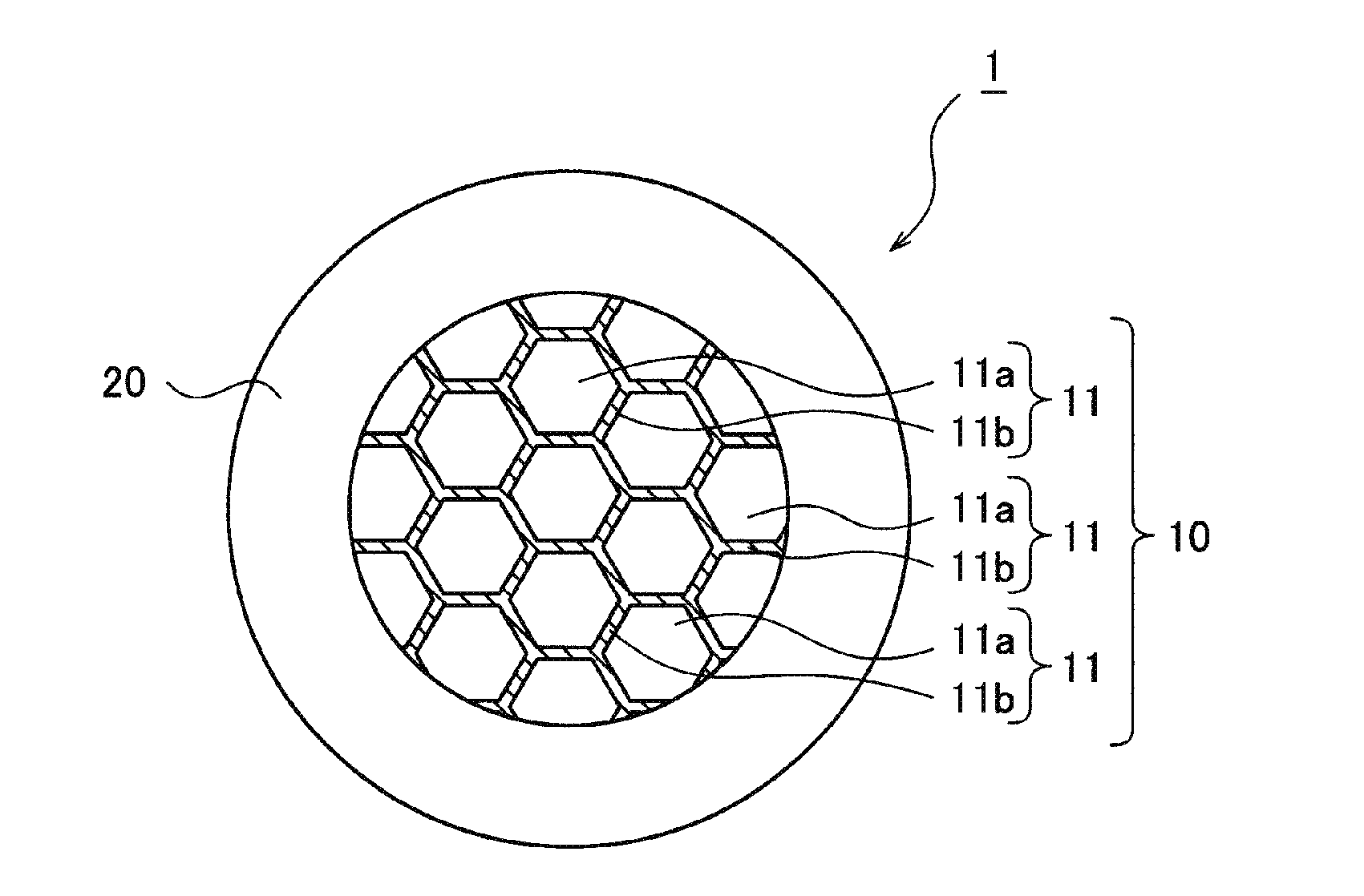
[0026]An embodiment will be described with reference to the accompanying drawings; however, the present invention is not limited to the embodiment. FIG. 1 is a sectional view illustrating an example of a high-frequency electric wire in the embodiment.

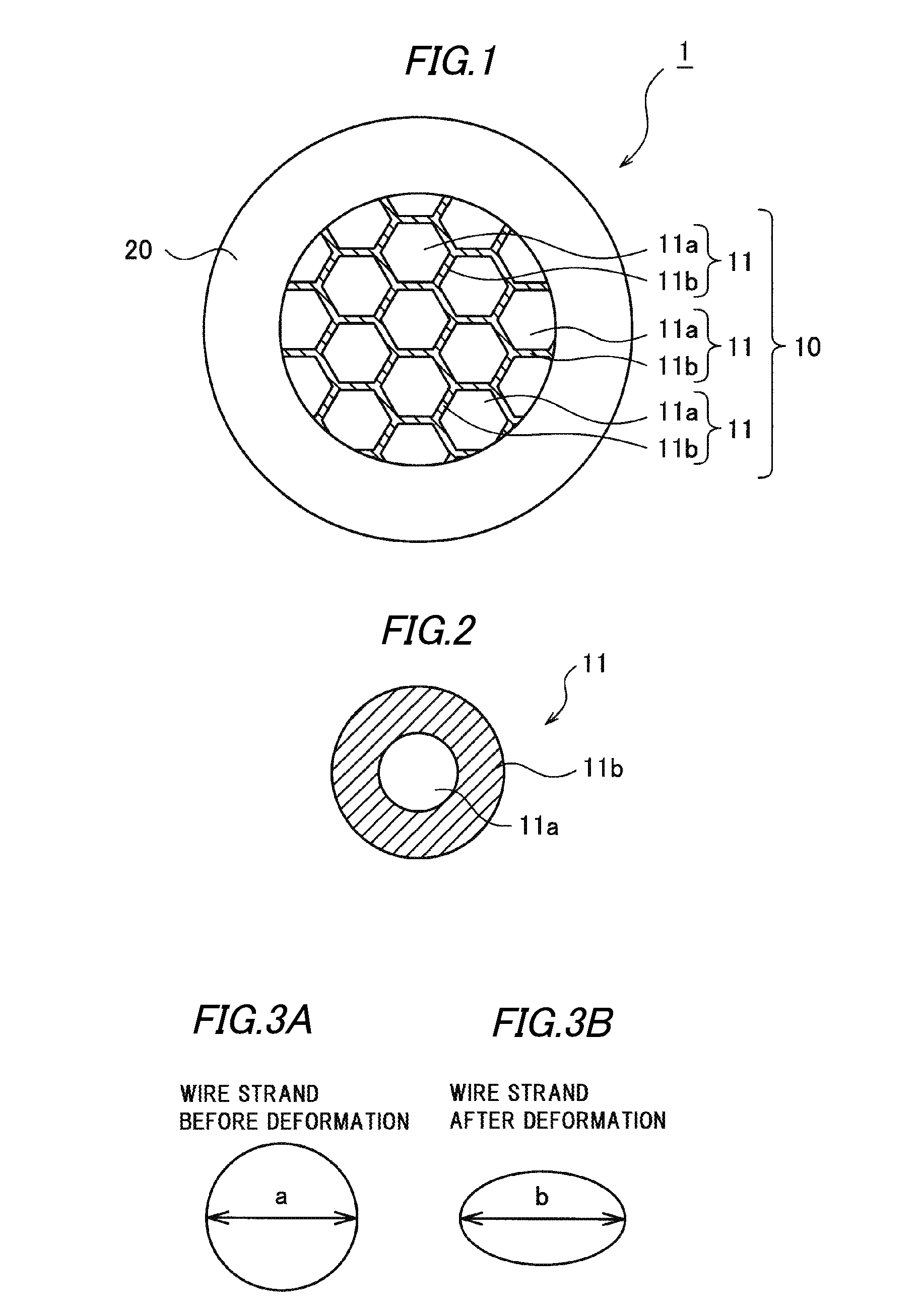
[0027]As illustrated in FIG. 1, a high-frequency electric wire 1 in the embodiment includes a conductor 10, and an insulating sheath 20 with which the insulator 10 is coated. The conductor 10 is obtained by compressing multiple wire strands 11. FIG. 2 is a sectional view illustrating the wire strand in FIG. 1. As illustrated in FIG. 2, the wire strand 11 is obtained by coating the outer circumference of a wire rod 11a (which is made of insulating resin) with a metal layer 11b. For example, the wire rod 11a is made of a polyarylate fiber, and the metal layer 11b is made of copper.

[0028]Gaps between the wire strands 11 are eliminated by compressing the wire strands 11, resulting in a reduction in the diameter of the high-frequency electri...


PUM

PropertyMeasurementUnit
diameteraaaaaaaaaa
depthaaaaaaaaaa
thicknessaaaaaaaaaa

Abstract

A high-frequency electric wire is provided with a conductor which formed by compressing multiple wire strands, each of which is obtained by coating an outside of a wire rod made of insulating resin with a metal layer, and a sheath provided on the conductor. Each of the wire strands of the conductor is compressed in such a way that a deformation ratio of the wire strand exceeds 0% and is 20% or less. The compression is performed, for example, during bundling and sheathing of the multiple wire strands.

Description

CROSS-REFERENCES TO RELATED APPLICATION[0001]This application is a continuation of International Patent Application No. PCT / JP2014 / 069347 filed on Jul. 22, 2014, claiming priority from Japanese Patent Application No. 2013-151247 filed on Jul. 22, 2013, the contents of which are incorporated herein by reference.BACKGROUND[0002]1. Field of the Invention[0003]The present invention relates to a high-frequency electric wire, a manufacturing method thereof, and a wire harness.[0004]2. Description of Related Art[0005]In the related art, a litz wire used to transmit high-frequency signals is known. The litz wire includes a conductor obtained by twisting together multiple wire strands, each of which is obtained by coating a metal conductor with an insulating layer. Typically, high-frequency signals are known to flow only through a vicinity of a surface of a conductor due to a skin effect during transmission of the high-frequency signals. Since the litz wire includes the conductor formed of t...

Claims


Application Information

Patent Timeline
Patent Type & Authority Applications(United States)
IPC IPC(8): H01B7/30H01B13/00H01B7/00
CPCH01B7/303H01B13/0006H01B7/0045
Inventor KONDO, HIROKI
Owner YAZAKI CORP
Why Eureka
Try Eureka