Deterministic assembly of complex, three-dimensional architectures by compressive buckling

a three-dimensional architecture and deterministic assembly technology, applied in the field of deterministic assembly of complex three-dimensional architectures by compressive buckling, can solve the problems of difficult integration of more than one type of any material into a single structure, and the nature of these processes sets practical constraints on operating speed and overall addressable areas

Active Publication Date: 2016-05-19
THE BOARD OF TRUSTEES OF THE UNIV OF ILLINOIS +1
View PDF4 Cites 59 Cited by
  • Summary
  • Abstract
  • Description
  • Claims
  • Application Information

AI Technical Summary

Benefits of technology

[0015]In an aspect, a structure comprises a deformable substrate, such as a stretchable, flexible or elastic substrate, having a surface and a thin film structure supported by the surface; wherein the thin film structure is bound to the surface at a plurality of bonding regions and not bound to the surface at a plurality of non-bonding regions; wherein relaxation of the deformable substrate provides a compressive force that generates a predetermined three-dimensional form of the thin film structure; wherein the predetermined three-dimensional form is characterized by at least one region with a mode ratio greater than or equal to 0.2, optionally for some embodiments greater than or equal to 0.4, optionally for some embodiments greater than or equal to 0.6 and optionally for some embodiments greater than or equal to 0.8. In some embodiments, the predetermined three-dimensional form is characterized by at least one region having a mode ratio between 0.2 and 1.2, or between 0.2 and 1.1, or between 0.2 and 0.8, or between 0.2 and 0.5. In an embodiment, relaxation of a deformable substrate reduces a state or amount of strain in the substrate and induces a change in one or more physical dimensions of a thin film structure. For example, relaxation of a deformable substrate, such as a stretchable substrate, may significantly reduce strain of the substrate (e.g., by at least 10%). In some embodiments, “complete relaxation” of the deformable substrate occurs when the strain of the substrate is approximately zero (e.g., less than 2%, or less than 1%).
[0038]In an aspect, a method of making a three-dimensional structure comprises: providing a prestrained elastic substrate characterized by an anisotropic spatial distribution of state of strain; the substrate having a receiving surface; providing a thin film structure to the receiving surface, the thin film structure having a geometry allowing conversion into a predetermined three-dimensional complex shape upon application of an anisotropic compressive force; and allowing the prestrained elastic substrate to relax, thereby generating the anisotropic compressive force for making the three-dimensional structure.
[0058]In an embodiment, the assembly substrate is an elastomeric substrate. In an embodiment, the first state of the assembly substrate is achieved by expanding the elastomeric substrate. In an embodiment, the step of transitioning the assembly substrate from the first state into the second state comprises allowing the assembly substrate to at least partially relax.

Problems solved by technology

Applicability of these latter methods, however, only extends directly to materials that can be formulated as inks or patterned by exposure to light / energetic particles, and indirectly to those that can be deposited onto or into sacrificial 3D structures formed with these materials.
Integration of more than one type of any material into a single structure can be challenging.
Furthermore, the serial nature of these processes sets practical constraints on operating speeds and overall addressable areas.
In addition, of the many methods for fabricating such structures, few are compatible with the highest performance classes of electronic materials, such as monocrystalline inorganic semiconductors, and only a subset of these can operate at high speeds, across length scales, from centimeters to nanometers.
These schemes are, however, not directly applicable to many technologically important types of materials, such as semiconductors or metals.
In most cases, however, such approaches are irreversible and offer limited control of parameters such as the folding angle, or folding rate.

Method used


Image

  • Deterministic assembly of complex, three-dimensional architectures by compressive buckling
  • Deterministic assembly of complex, three-dimensional architectures by compressive buckling
  • Deterministic assembly of complex, three-dimensional architectures by compressive buckling

Examples


example 1

Deterministic Assembly of Functional Micro / Nanomaterials into Complex, Three-Dimensional Architectures by Compressive Buckling

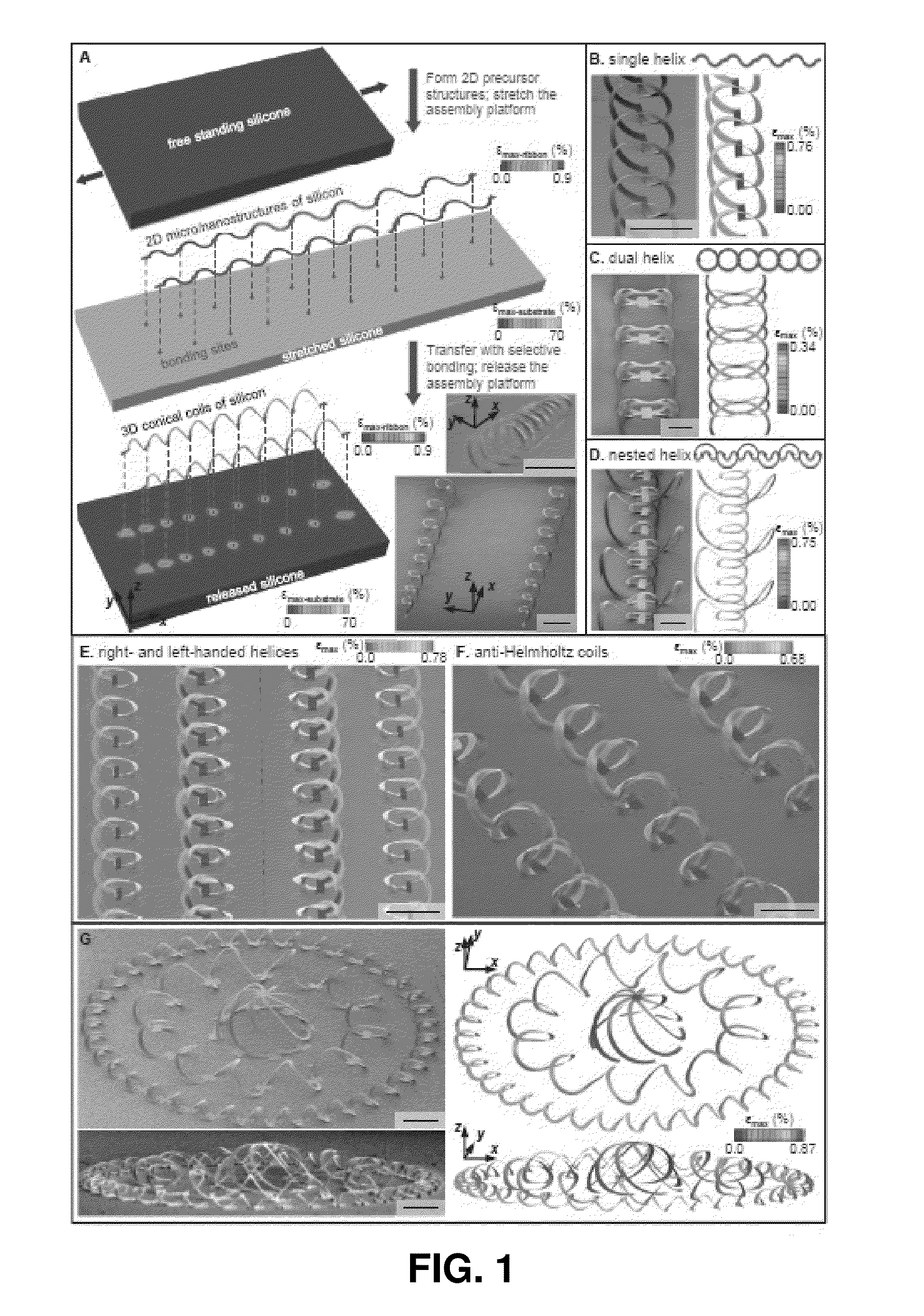
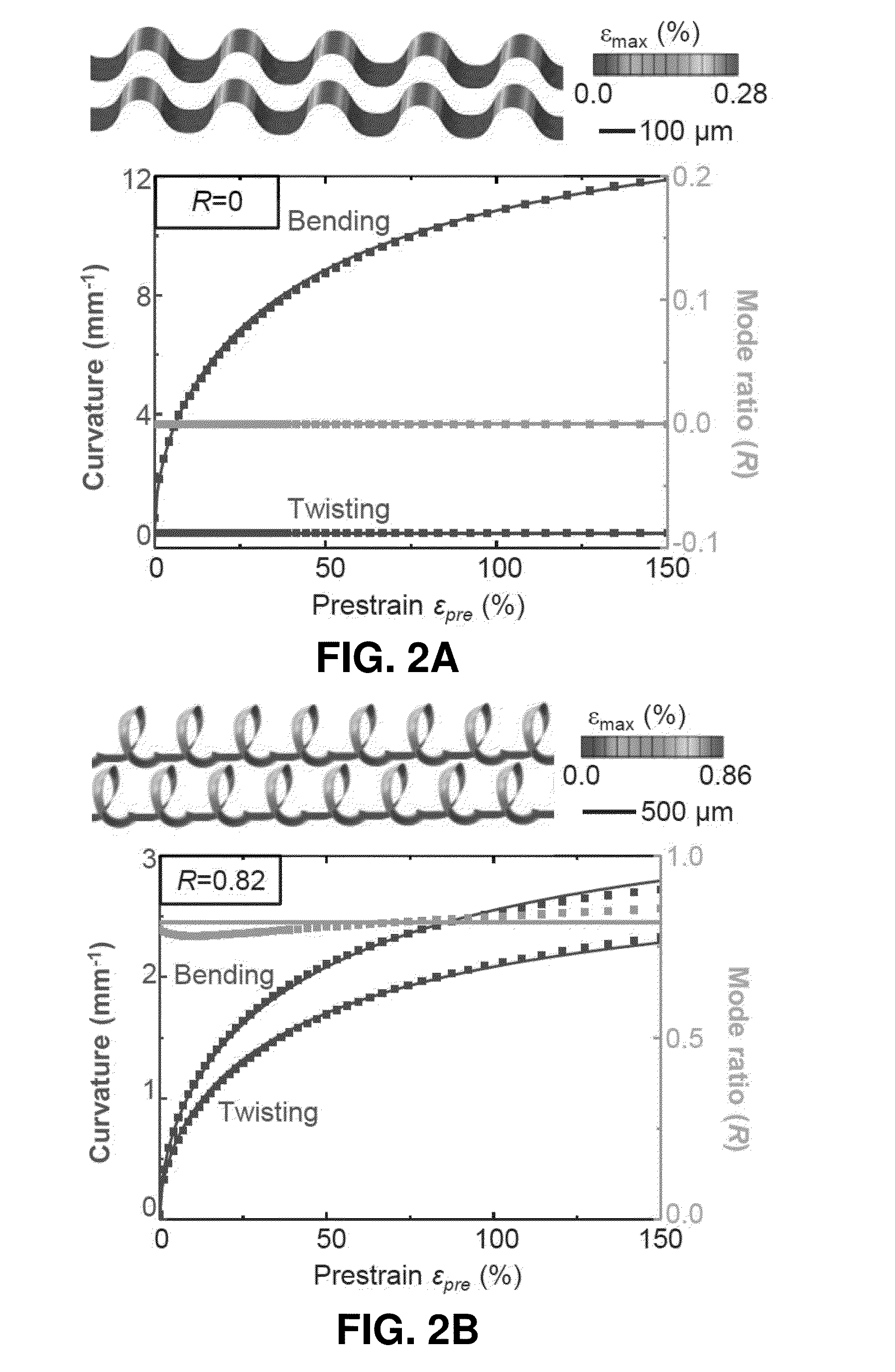
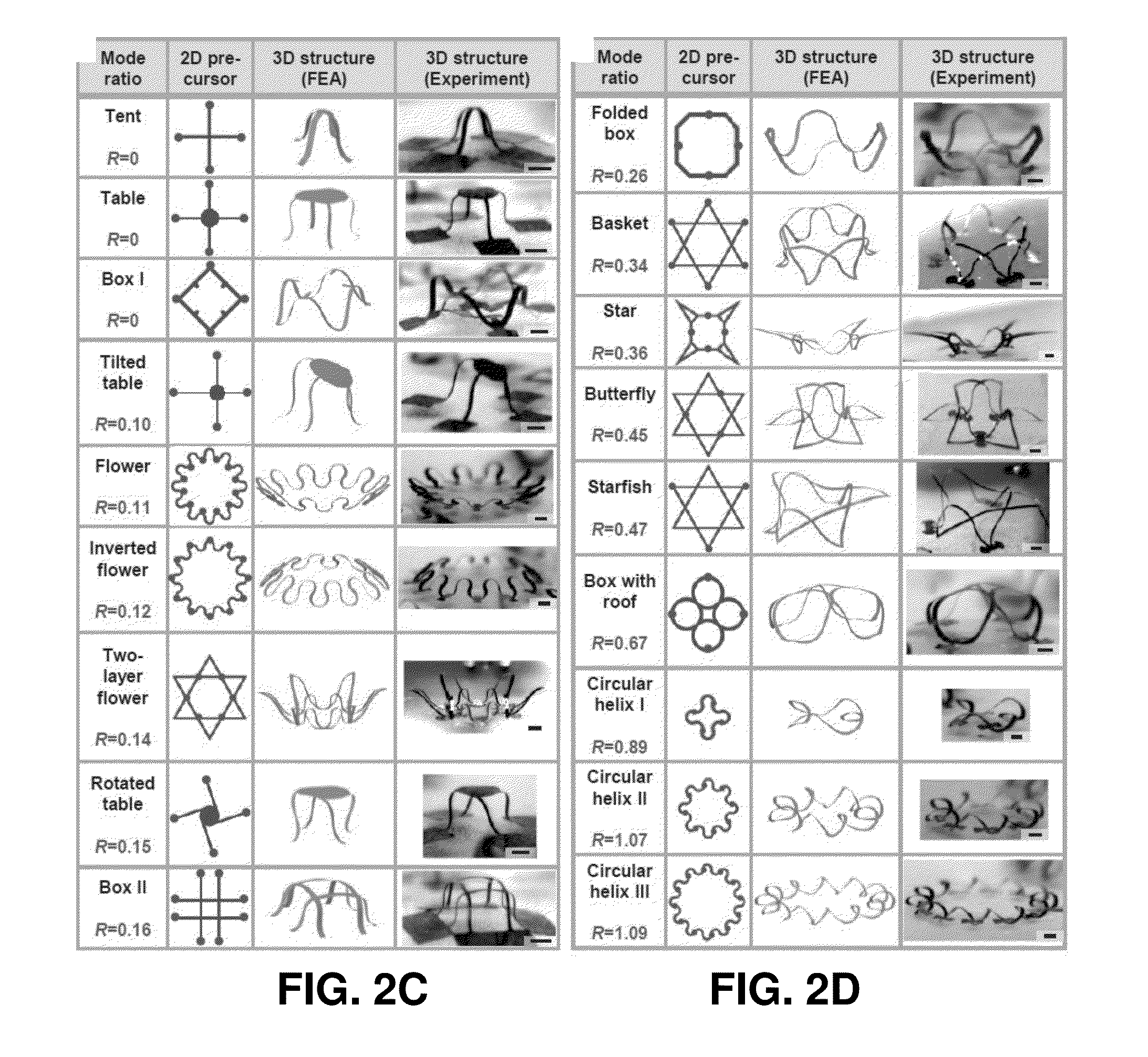
[0196]Complex, three dimensional (3D) assemblies of nanomaterials form naturally in all biological systems, where they provide essential functions in even the most basic forms of life. Compelling opportunities exist for analogous 3D structures in man-made devices, but design options are constrained by comparatively primitive capabilities in materials growth and assembly. Here we report simple, rapid routes to previously inaccessible classes of 3D architectures in advanced materials, with characteristic dimensions that range from nanometers to centimeters and areas that span square centimeters or more. The approach relies on geometric transformation of two dimensional (2D) micro / nanostructures into extended 3D layouts by controlled processes of substrate-induced compressive buckling. Demonstrations include combined experimental and theoretical studies of more ...

example 2

A Mechanically Driven Form of Kirigami as a Route to 3D Mesostructures in Micro / Nanomembranes

[0269]Abstract

[0270]Assembly of three-dimensional (3D) micro / nanostructures in advanced functional materials has important implications across broad areas of technology. Existing approaches are compatible, however, only with narrow classes of materials and / or 3D geometries. This example introduces ideas for a form of Kirigami that allows precise, mechanically driven assembly of 3D mesostructures of diverse materials from 2D micro / nanomembranes with strategically designed geometries and patterns of cuts. Theoretical and experimental studies demonstrate applicability of the methods across length scales from macro to nano, in materials ranging from monocrystalline silicon to plastic, with levels of topographical complexity that significantly exceed those that can be achieved in any other way. A broad set of examples includes 3D silicon mesostructures and hybrid nanomembrane-nanoribbon systems, ...

example 3

Origami of Micro / Nanomaterials Through Controlled Buckling

[0348]In this example, mechanical buckling schemes for autonomic origami-inspired assembly are presented in comprehensive theoretical and experimental studies, with examples in 3D architectures with a broad range of topologies and material compositions, including high-performance semiconductor nanomaterials. The resulting engineering options in the construction of functional 3D mesostructures have important implications for advanced microsystem technologies.

[0349]Origami, the ancient Japanese art of paper folding, involves the transformation of planar paper sheets into macroscopic three-dimensional (3D) sculptures with diverse topologies.[1] Origami is now a topic of rapidly growing interest in the scientific and engineering research communities, due to its potential or use in a broad range of applications, from self-folding microelectronics,[2-4] deformable batteries,[5, 6] and reconfigurable metamaterials,[7] to artificial ...


PUM

PropertyMeasurementUnit
thicknessaaaaaaaaaa
thicknessaaaaaaaaaa
thicknessaaaaaaaaaa

Abstract

Origami- and Kirigami-inspired assembly of predetermined three-dimensional forms is presented in comprehensive theoretical and experimental studies, with examples of a broad range of topologies and material compositions. The resulting engineering options in the construction of functional 3D structures have important implications for advanced microsystem technologies.

Description

CROSS-REFERENCE TO RELATED APPLICATIONS[0001]This application claims the benefit of priority from U.S. Provisional Patent Application No. 62 / 080,897, filed Nov. 17, 2014, which is hereby incorporated by reference in its entirety.STATEMENT REGARDING FEDERALLY SPONSORED RESEARCH OR DEVELOPMENT[0002]This invention was made with government support under DE-FG02-07ER46471 awarded by the U.S. Department of Energy, CMMI-1400169 awarded by the National Science Foundation and R01EB019337 awarded by the National Institutes of Health. The government has certain rights in the invention.BACKGROUND[0003]Controlled formation of 3D functional structures is a topic of broad and increasing interest, particularly in the last decade, due to important envisioned uses in nearly every type of micro / nanosystem technology, from biomedical devices to microelectromechanical components, metamaterials, sensors, electronics and others. Although volumetric optical exposures, colloidal self-assembly, residual stre...

Claims


Application Information

Patent Timeline
Patent Type & Authority Applications(United States)
IPC IPC(8): B29C61/06B29C65/48B32B27/40B32B1/00B32B27/28
CPCB29C61/0616B32B1/00B32B27/283B32B27/40B29L2007/008B29C65/48B29K2105/256B29L2031/756B32B27/285B29C61/006H05K1/0283
Inventor ROGERS, JOHN A.XU, SHENGYAN, ZHENGZHANG, YIHUIHUANG, YONGGANG
Owner THE BOARD OF TRUSTEES OF THE UNIV OF ILLINOIS
Why Eureka
Try Eureka