Method of constructing a geological model

a geological model and model technology, applied in the field of oil exploration, can solve the problems of inability to continuously represent the results, and the calculation time of conjugate gradients is very expensiv

Active Publication Date: 2016-05-19
INST FR DU PETROLE
View PDF7 Cites 22 Cited by
  • Summary
  • Abstract
  • Description
  • Claims
  • Application Information

AI Technical Summary

Problems solved by technology

However, the interpolation of sparse measurements on a grid by B-spline function turns out to be very sensitive to the choices of the parametrization of the inverse problem (number of parameters of the B-spline function, regularizing weight of the objective function to be minimized in particular) and very often requires several manual interventions by the user before obtaining a geologically plausible result.
One of the main drawbacks of this procedure res

Method used


Image

  • Method of constructing a geological model
  • Method of constructing a geological model
  • Method of constructing a geological model

Examples


examples of application

[0122]The characteristics and advantages of the method according to the invention will be more clearly apparent on reading the examples of application hereinafter.

example 1

Case Without Faults

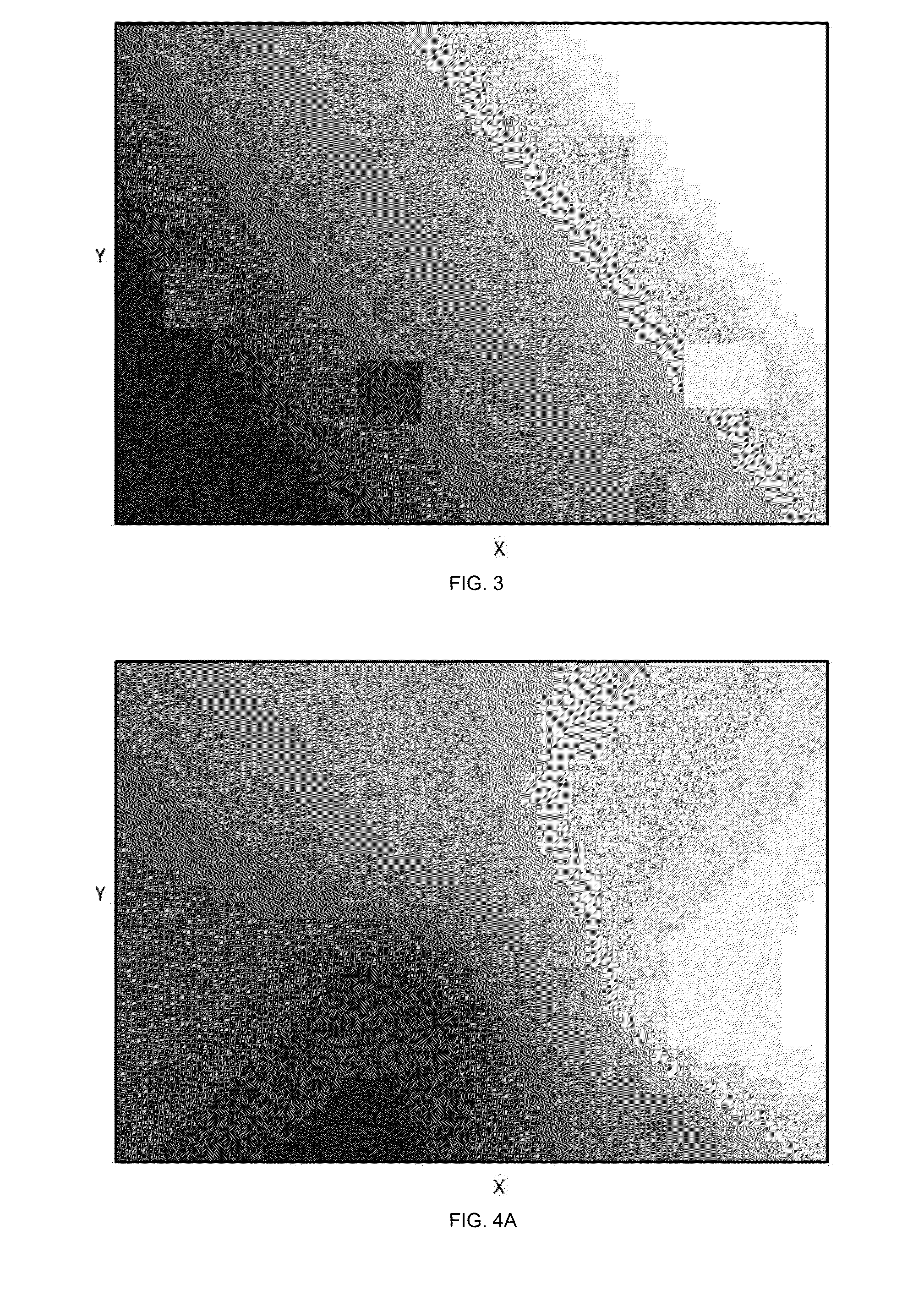
[0123]In this example, a subterranean formation exhibiting a single boundary of beds is considered. Sparse measurements of the geometry of this boundary of beds are available on a fine grid G0 formed of 500 by 700 mesh cells, i.e. a number N0 of mesh cells of 350 000. For this illustrative example, a number of empty mesh cells N″0 of 340 000 will be considered. In order to complete the empty mesh cells of the grid of interest, one chooses to solve, by the conjugate gradient procedure, an inverse problem, such as described in the previous step 1.3.2), based on the minimization of the second derivatives.

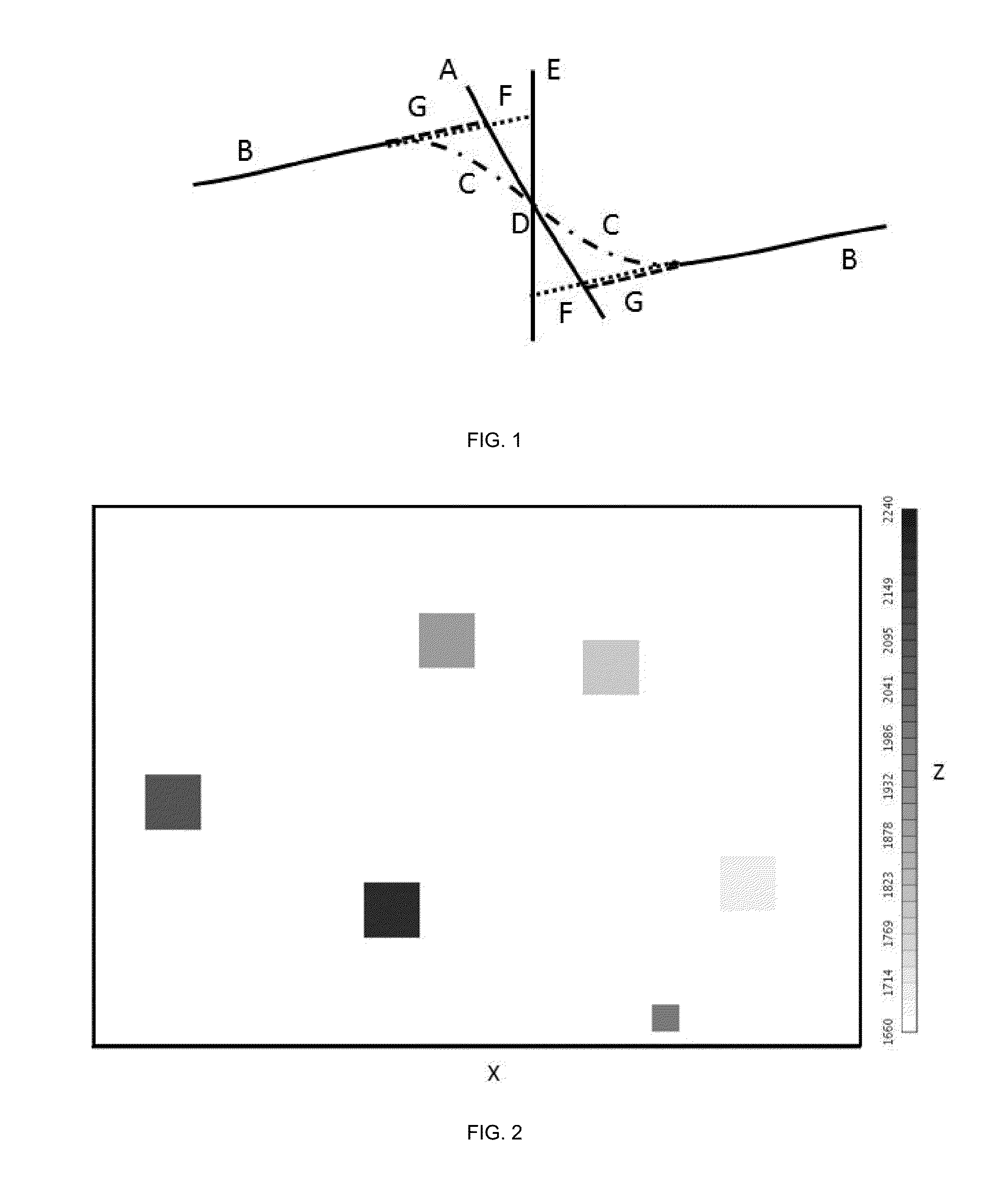
[0124]FIG. 2 shows, by squares hatched to greater or lesser extent, the N′0 measurements of the geometry of the considered boundary of beds which are carried out on the fine grid G0. It may thus be observed that the 10 000 measurements of the geometry have been carried out in six very distinct zones and that the measured depth varies between 1700 and 2200 m.

[0125]In ...

example 2

Case with Faults

[0131]Through this example, we propose to determine the geometry of the same boundary of beds as that described in the previous example, but in the case where five faults are present.

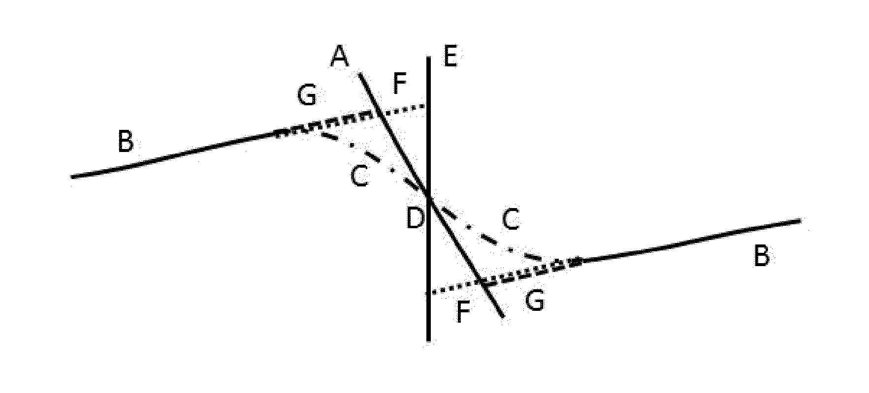
[0132]FIG. 7 presents the location of the N′0 measurements (hatched squares) with respect to the five fault planes in question (curved lines). FIG. 8 presents the result of the method according to the invention applied with the same characteristics as in the previous example, but taking the faults into account, as is described in a variant of the method according to the invention. In particular, a step of adaptation to the case of the faults of the step described in section 1.3.1 of initialization of each inverse problem has been implemented. It may thus be noted in this Figure that the method according to the invention makes it possible to take account of the location of the faults, by interrupting the process of interpolation / extrapolation of a boundary of beds at the level of the faul...


PUM


Abstract

Method of constructing a geological model of a subterranean formation formed of at least two sedimentary beds.
On the basis of sparse measurements of the geometry of boundaries of beds of a subterranean formation carried out on a grid, values of the geometry of each bed at any point of the grid are calculated according to at least the following steps: a succession of coarser and coarser grids is defined, constructed on the basis of the grid of interest; then, proceeding from the coarsest grid to the grid of interest, the geometry of the boundaries of each bed is determined by solving an inverse problem initialized with the result obtained for the previous coarser grid. Next, on the basis of the completed geometry of each boundary of beds on the grid of interest, the geological model of the formation is constructed.
Application especially to the exploration and exploitation of oilfields.

Description

[0001]The present invention relates to the sector of oil exploration, more particularly the sector of the exploration and exploitation of oil reservoirs or geological gas storage sites.[0002]The study of an oil field requires the construction of a representation of the subterranean formation studied, also called a geological model in the broad sense or else a geomodel. These models, well known and widely used in the oil industry, make it possible to determine numerous technical parameters relating to the search for, study or exploitation of a reservoir, of hydrocarbons for example. Thus, a geological model has to be representative of the structure of a reservoir as well as of its behavior. It is thus possible for example to determine the zones which have the most chance of containing hydrocarbons, the zones in which it may be opportune to drill an injection well to improve the recovery of the hydrocarbons, the type of tools to be used, the properties of the fluids used and recovered...

Claims


Application Information

Patent Timeline
IPC IPC(8): G01V99/00E02D1/02E02B1/02
CPCG01V99/005E02D1/022E02B1/02G01V1/282G01V1/301
Inventor LEGER, MICHEL
Owner INST FR DU PETROLE
Why Eureka
Try Eureka