
Medical imaging device and method for operating a medical imaging device

Inactive Publication Date: 2016-05-26
SIEMENS AG
View PDF5 Cites 1 Cited by
  • Summary
  • Abstract
  • Description
  • Claims
  • Application Information

AI Technical Summary

Benefits of technology

The patent text discusses a way to improve the accuracy and reliability of medical imaging devices without adding any extra hardware. This is done by using a method called self-testing, which helps to detect and evaluate errors in the device. This approach also increases patient safety and helps gather data on the typical usage of the device. Overall, this method simplifies the process of ensuring the device is performing correctly.

Problems solved by technology

In general, this is brought about by complicated shielding measures.
A note to the user of the medical device is not sufficient here.

Method used


Image

  • Medical imaging device and method for operating a medical imaging device
  • Medical imaging device and method for operating a medical imaging device

Examples


Embodiment Construction

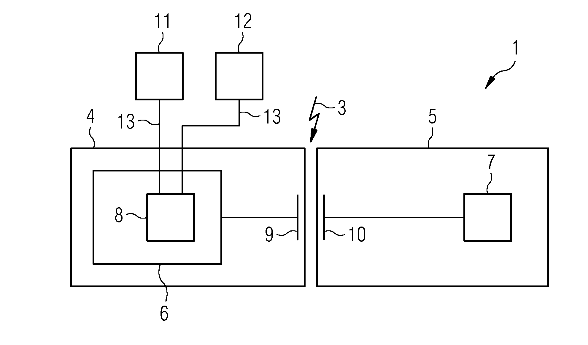
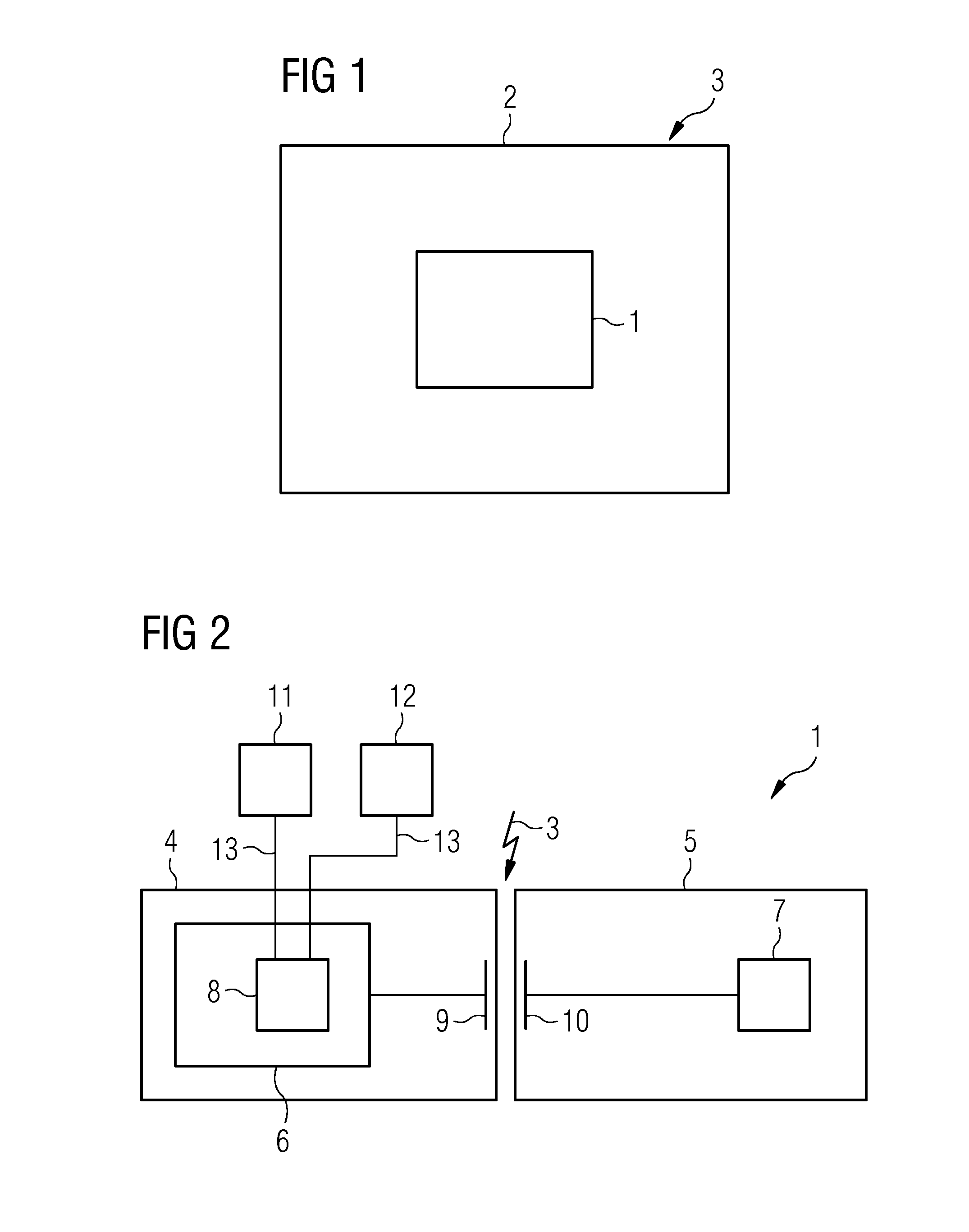
[0023]FIG. 1 shows a block diagram of one embodiment of a medical imaging device 2 (e.g., a computed tomography scanner) with a contactless data transmission apparatus 1 for transmitting data (e.g., from an x-ray detector) to an image generation unit not depicted here. The medical imaging device 2 may have a plurality of such contactless data transmission apparatuses. In addition to image data, control data may be transmitted, and data transmission is thus permanently present, even without image recording.

[0024]As a result of external interference sources such as, for example, cellular telephones or WLAN routers, an interference field 3 (e.g., electric, magnetic, electromagnetic) may scatter into the contactless data transmission apparatus 1 and thus interfere with the data transmission and hence the operation of the medical imaging device 2.

[0025]FIG. 2 shows a block diagram of one embodiment of the data transmission apparatus 1 according to FIG. 1. Useful data and / or control data ...


PUM


Abstract

A medical imaging device with a contactless data transmission device that registers interference fields acting thereon is provided. The device includes a bit error registration unit of the data transmission apparatus. The bit error registration unit is embodied and programmed to establish the bit error rate of the data transmission apparatus caused by the interference fields, and to output a warning signal when a predeterminable threshold of the bit error rate is exceeded.

Description

[0001]This application claims the benefit of DE 10 2014 224 010.7, filed on Nov. 25, 2014, which is hereby incorporated by reference in its entirety.FIELD[0002]The present embodiments relate to a medical imaging device with a contactless data transmission device and an associated method for operating a medical imaging device.BACKGROUND[0003]One field of application of the present embodiments relates to the data transmission between the rotating part and the stationary part of a computed tomography scanner. During operation of the computed tomography scanner, the data registered by the x-ray detectors is to be transmitted from the rotating part to the stationary part of the computed tomography scanner in order to be processed further there. Relatively large amounts of data are to be transmitted within a short period of time.[0004]Many currently available computed tomography scanners use a contactless “slip ring” device for data transmission, as is known, for example, from U.S. Pat. N...

Claims


Application Information

Patent Timeline
IPC IPC(8): A61B6/00A61B5/055H04L29/08A61B6/03H04N1/00G16Z99/00
CPCA61B6/56A61B6/032A61B5/055H04N1/00214H04L67/12A61B6/586A61B5/0013A61B2560/0276G16H40/63G16Z99/00
Inventor LUTHARDT, THOMASREPP, HELMUTSITZMANN, ROBERT
Owner SIEMENS AG
Features
  • Generate Ideas
  • Intellectual Property
  • Life Sciences
  • Materials
  • Tech Scout
  • Unparalleled Data Quality
  • Higher Quality Content
  • 60% Fewer Hallucinations
Learn More