Resistance spot welding method

a welding method and resistive spot technology, applied in welding/soldering/cutting articles, electrode supporting devices, manufacturing tools, etc., can solve problems such as equipment malfunction, surface quality impairment, and current value at which internal sputter is generated by welding using a singl

Inactive Publication Date: 2016-05-26
NIPPON STEEL CORP
View PDF5 Cites 14 Cited by
  • Summary
  • Abstract
  • Description
  • Claims
  • Application Information

AI Technical Summary

Benefits of technology

[0017]The resistance spot welding method of the present invention enables a wide appropriate current range to be secured, even in cases in which an inverter direct current source is employed to perform spot welding of sheet assemblies of overlapped steel sheet including a high tensile steel sheet.

Problems solved by technology

In both cases, the surface quality of the vehicle body is impaired by the sputter scattering and adhering to the automobile vehicle body.
Sputter adhering to moving parts of a welding robot is also a cause of equipment malfunction.
Needle shaped surface sputter remaining on the spot weld surface causes damage to automobile wiring harnesses and the like, and therefore needs to be ground off with a grinder.
However, the current value at which internal sputter is generated by welding using a single stage current pass is low with high tensile steel sheets using an inverter direct current method, and there is significant narrowing of the appropriate current range.

Method used


Image

  • Resistance spot welding method
  • Resistance spot welding method
  • Resistance spot welding method

Examples


examples

[0108]Explanation follows regarding examples; however, the present invention is not limited to these examples.

examples 1

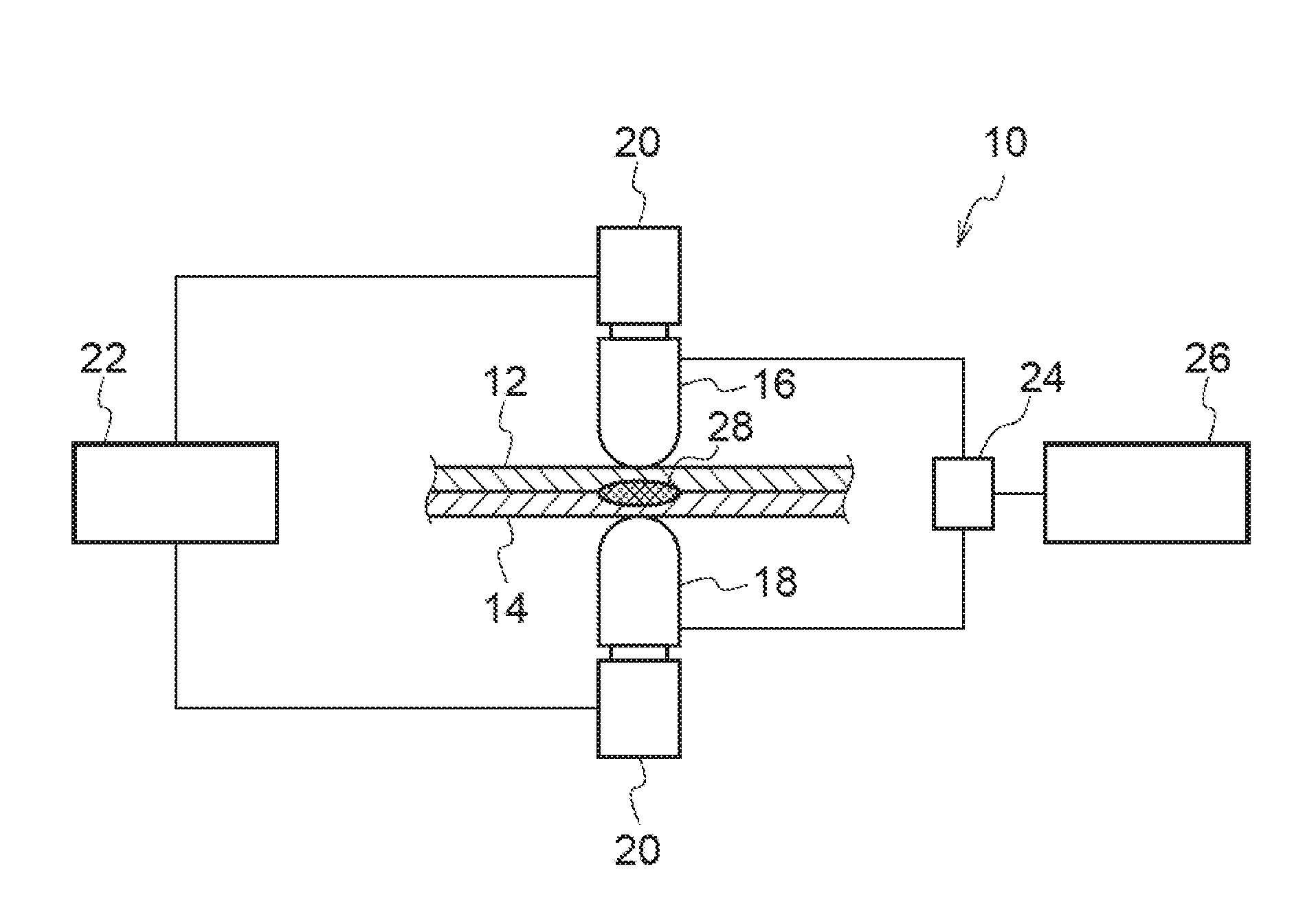
[0109]The welding machine employed in the present examples is an inverter direct current spot welding machine that uses a servo press method, and includes DR-type electrodes (alumina dispersion strengthened copper) having an outer-circumferential radius of curvature of 6 mm, and a tip radius of curvature of 40 mm. The material to be welded is two overlapped sheets of aluminum-plated 1500 MPa grade hot stamped steel sheets (the plating amount prior to hot stamping was 40 g / m2 per side, and the heating conditions are heating inside a gas furnace at 900° C. for 4 minutes) with a sheet thickness of 1.2 mm and a size of 30 mm×100 mm.

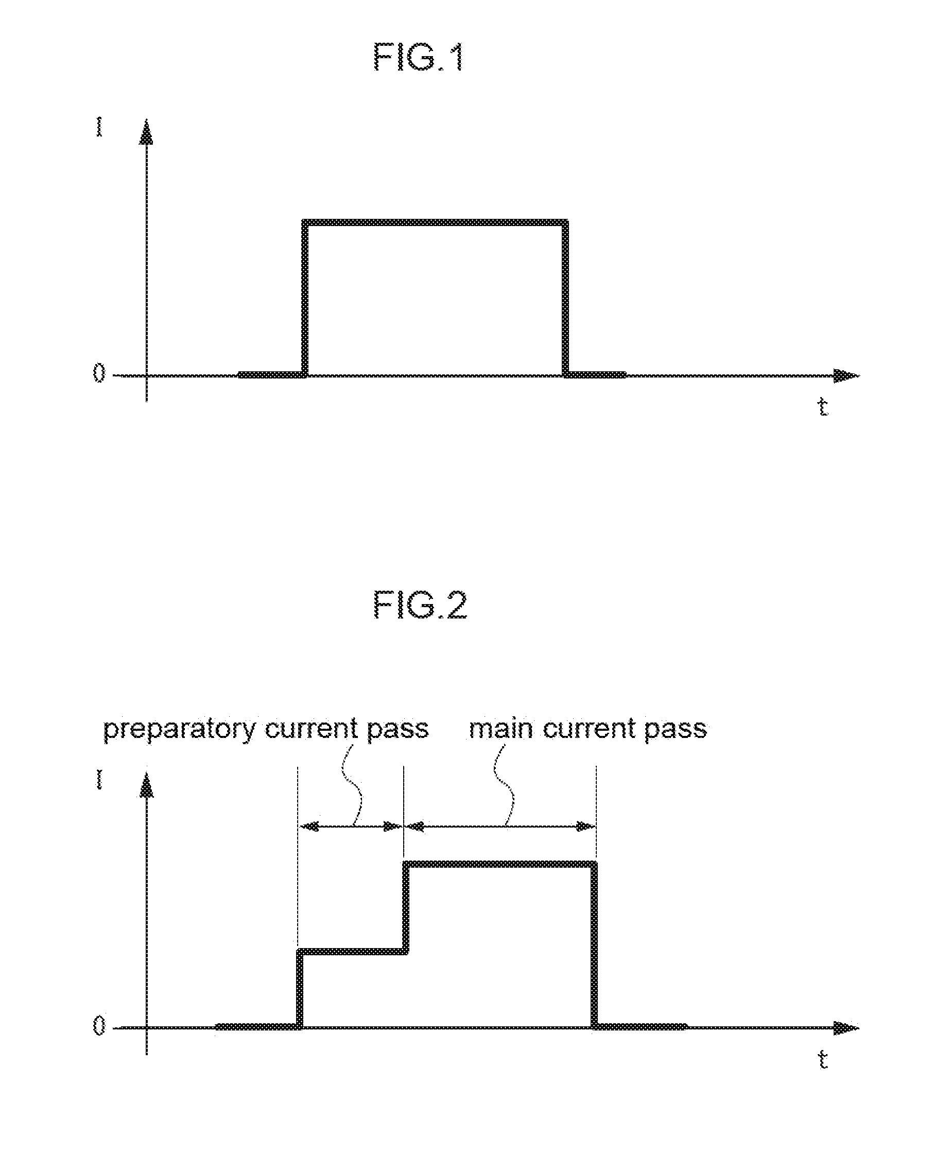
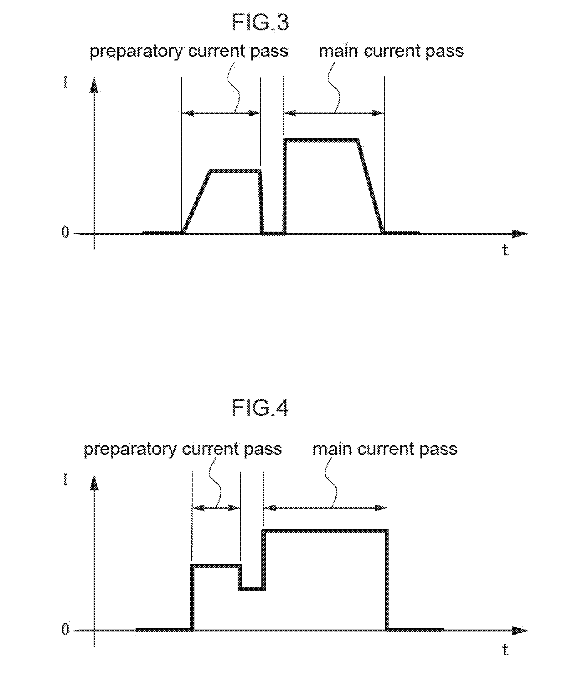
[0110]The welding methods are listed in Table 1. Although Test Nos. 6, 7 include a preparatory current pass prior to the continuous current pass process, they are tests in which a two stage current pass is performed without a stop time between the preparatory current pass and the continuous current pass processes. Test No. 8 is configured with a current pass ...

examples 2

[0114]The welding machine employed in the present examples is the same as that of Examples 1. The material to be welded was three overlapped sheets, these being a GA-plated 270 MPa grade steel sheet with a sheet thickness of 0.7 mm and a size of 30 mm×100 mm, a GA-plated 1500 MPa grade hot stamped steel sheet with a sheet thickness of 1.2 mm (the plating amount prior to hot stamping was 55 g / m2 per side, and the heating conditions were the same as those of Examples 1), and an unplated 440 MPa grade steel sheet with a sheet thickness of 1.4 mm. The welding methods are listed in Table 2. The current pass methods of the comparative examples are similar to those of Examples 1. In both the examples of the present invention and the comparative examples, the weld force was a constant value (300 kgf) in the pulsation process or the preparatory current pass, and in the continuous current pass process.

[0115]Testing and evaluation of the test results were performed similarly to in the Examples...


PUM

PropertyMeasurementUnit
current pass stop timeaaaaaaaaaa
currentaaaaaaaaaa
current pass timeaaaaaaaaaa

Abstract

A resistance spot welding method including: a pulsation process of clamping a sheet assembly of two or more overlapped steel sheets including at least one high tensile steel sheet using a pair of welding electrodes that are connected to a spot welding power source employing an inverter direct current method, and performing plural repetitions of current passing and current pass stopping, while pressing the steel sheets with the welding electrodes; and a continuous current pass process in which, after the pulsation process, current is passed continuously for a longer period of time than a maximum current pass time of the pulsation process, while pressing the steel sheets with the welding electrodes.

Description

CROSS-REFERENCE TO RELATED APPLICATIONS[0001]This application is a national stage application of International Application No. PCT / JP2014 / 067083, filed Jun. 26, 2014, which is incorporated herein by reference in its entirety, and which claims priority to Japanese Patent Application No. 2013-145380, filed on Jul. 11, 2013.TECHNICAL FIELD[0002]The present invention relates to a resistance spot welding method.BACKGROUND ART[0003]Automobile vehicle bodies are mainly assembled by joining pressed steel sheets together using spot welding. In spot welding used to assemble vehicle bodies, there are demands both to secure a nugget diameter according to the sheet thickness, and to suppress the occurrence of sputter.[0004]Sputter includes internal sputter (a phenomenon in which parent metal that has been melted by welding is scattered from the superimposed faces of the steel sheets) and surface sputter (a phenomenon in which parent metal that has been melted by welding is scattered from contact...

Claims


Application Information

Patent Timeline
Patent Type & Authority Applications(United States)
IPC IPC(8): B23K11/24B23K11/16
CPCB23K11/16B23K11/245B23K11/115B23K2101/18B23K2103/04B23K11/11B23K11/24
Inventor FUJIMOTO, HIROKIDIKAWA, HATSUHIKOYAMANAKA, SHINTARO
Owner NIPPON STEEL CORP
Why Eureka
Try Eureka