
Systems and methods of write cache flushing

a write cache and cache technology, applied in the direction of memory adressing/allocation/relocation, instruments, computing, etc., can solve the problem of inefficient use of storage capacity for storing padding in non-volatile memory, and achieve the effect of improving the efficiency of use of non-volatile memory storage capacity and avoiding significant delays

Active Publication Date: 2016-05-26
SANDISK TECH LLC
View PDF5 Cites 38 Cited by
  • Summary
  • Abstract
  • Description
  • Claims
  • Application Information

AI Technical Summary

Benefits of technology

The data storage device described in this patent has a controller, non-volatile memory, and a volatile write cache. The controller is responsible for filling a write block with data from pending write commands, after a flush command or a write command with force unit access (FUA) flag is received. This improves the efficiency of using the storage capacity of the non-volatile memory. The controller may start a timer to attempt to fill the write block and add padding to the data to fill the write block, while the timer expires. This precaution helps to avoid delays and ensures quicker processing.

Problems solved by technology

Since the padding is not data received from the host, storing the padding in the non-volatile memory is an inefficient use of storage capacity of the non-volatile memory.

Method used


Image

  • Systems and methods of write cache flushing
  • Systems and methods of write cache flushing
  • Systems and methods of write cache flushing

Examples


Embodiment Construction

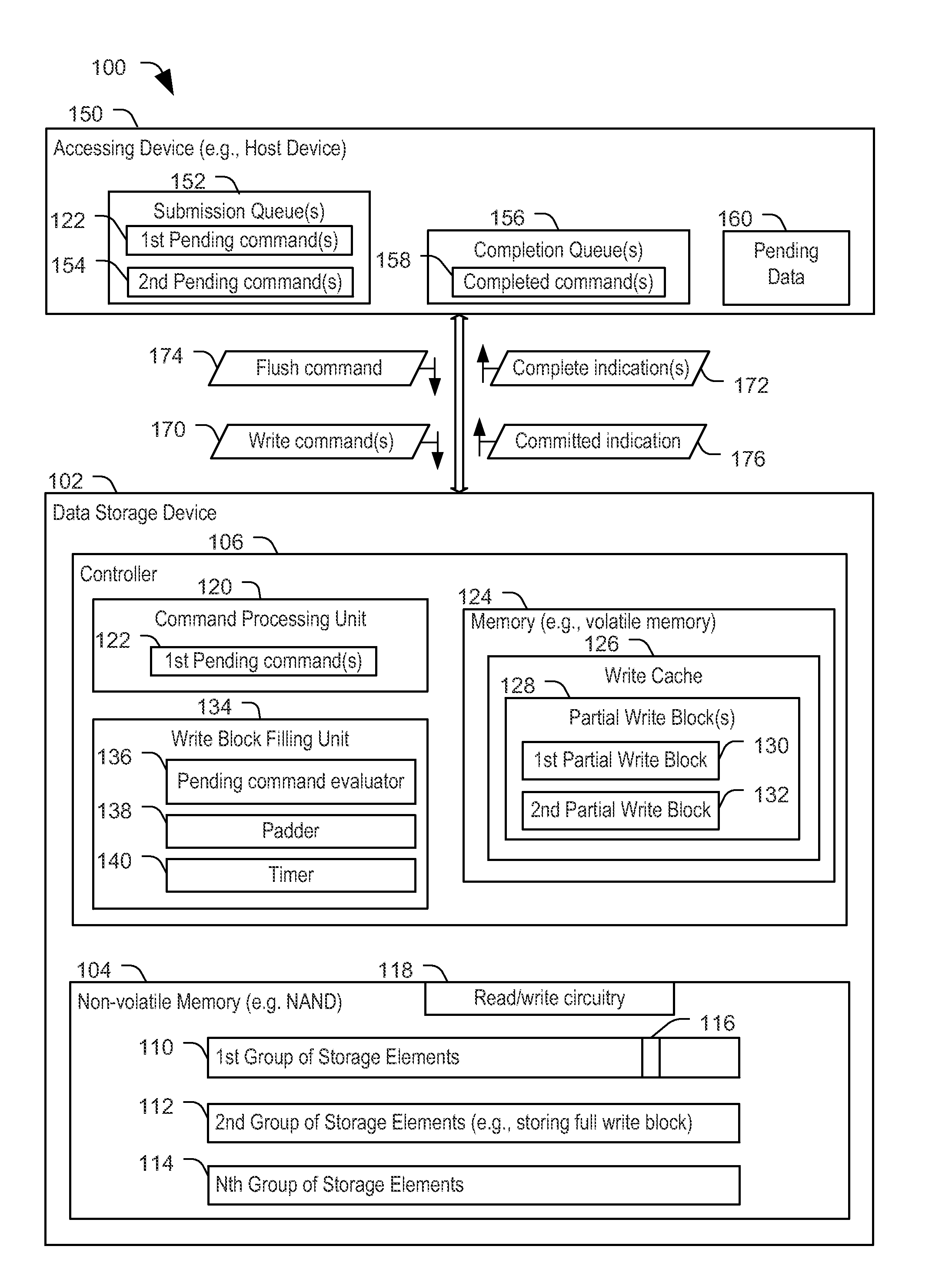
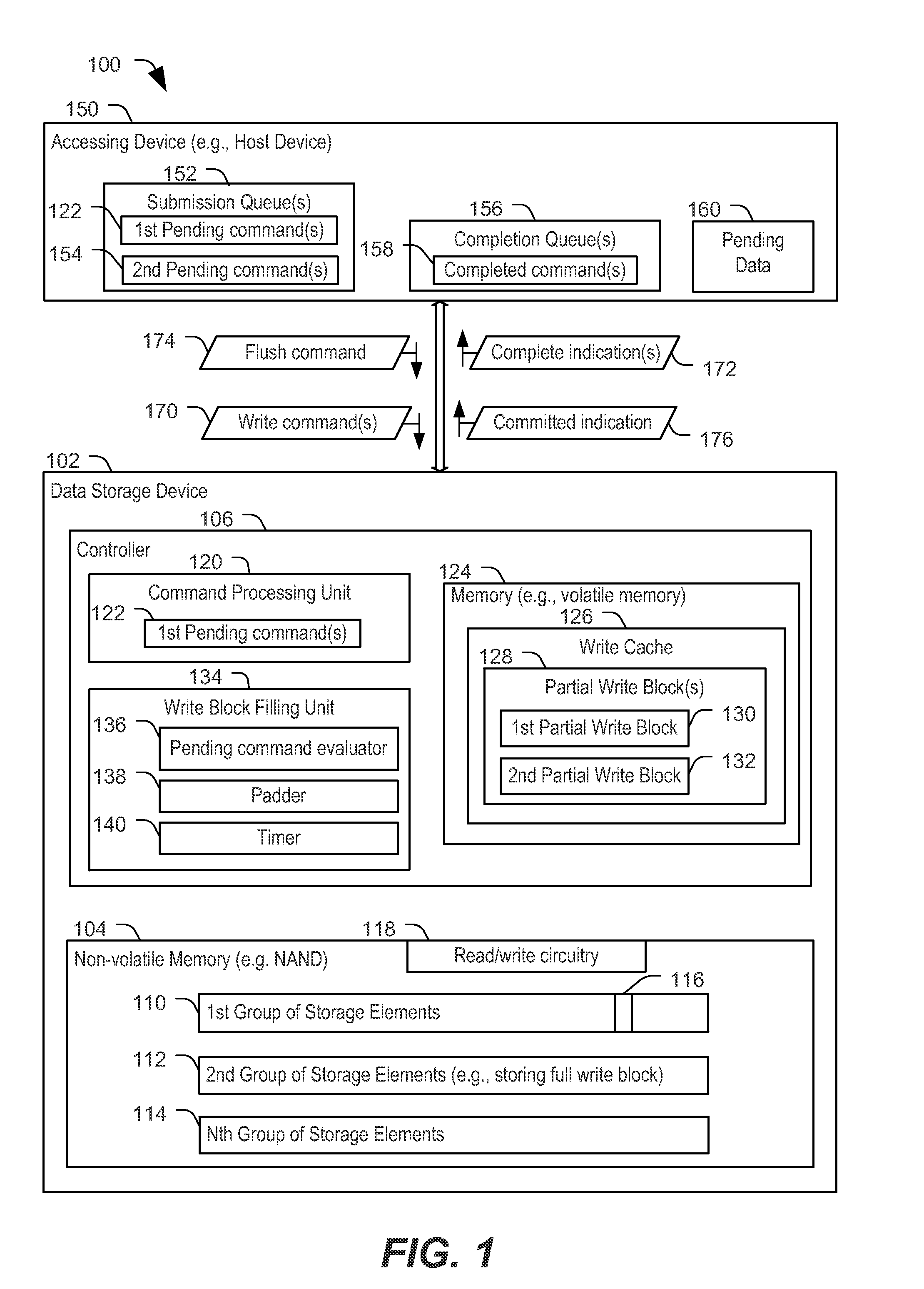
[0011]FIG. 1 is a block diagram of a first particular embodiment of a system 100 including a data storage device 102 configured to attempt to fill a write block using data associated with pending write commands. The data storage device 102 includes a controller 106 and a non-volatile memory 104. In a particular implementation, the non-volatile memory 104 is on a memory die that is separate from the controller 106 and is coupled to the controller 106 via a bus. In other implementations, the non-volatile memory 104 and the controller 106 are on a common die.

[0012]The non-volatile memory 104 may be use storage elements based on various memory technologies, such as, a Flash memory (e.g., NAND, NOR, Multi-Level Cell (MLC), Divided bit-line NOR (DINOR), AND, high capacitive coupling ratio (HiCR), asymmetrical contactless transistor (ACT), or other Flash memory technologies), a Resistive Random Access Memory (RRAM or ReRAM), or any other type of memory technologies. The storage elements of...


PUM


Abstract

A data storage device includes a write cache, a non-volatile memory, and a controller coupled to the write cache and to the non-volatile memory. The controller is configured to, responsive to receiving a command to flush particular data from the write cache, attempt to fill a write block of data using the particular data and pending data obtained after receipt of the command.

Description

FIELD OF THE DISCLOSURE[0001]The present disclosure is generally related to flushing a write cache of a data storage device.BACKGROUND[0002]Generally, data storage devices are configured to write data to multiple storage elements concurrently, rather than, for example, writing data to one storage element at a time. For such data storage devices, the smallest set of storage elements that can be written at a time may be referred to as a write block. Since individual write commands may be associated with less than a full write block of data, a data storage device may store data that is to be written to a non-volatile memory in a volatile cache. After sufficient data is available in the cache to fill a write block, a full write block of data may be written from the volatile cache to the non-volatile memory.[0003]In certain circumstances, a device (e.g., a host) coupled to the data storage device may issue a command to clear the cache (such as a flush command), or the device may issue a ...

Claims


Application Information

Patent Timeline
IPC IPC(8): G06F12/12
CPCG06F12/12G06F2212/69G06F2212/1041G06F12/0844G06F12/0868G06F12/0246
Inventor VISHNE, GADIEREZ, ERANROZENTAL, ROMANMARIMONT, POLINAHAHN, JUDAH GAMLIEL
Owner SANDISK TECH LLC
Learn More