Method for transferring a sheet between two conveyors

Inactive Publication Date: 2016-06-02
OCE TECH
View PDF3 Cites 6 Cited by
  • Summary
  • Abstract
  • Description
  • Claims
  • Application Information

AI Technical Summary

Benefits of technology

[0021]It is found that said stiffness of the curl state is related to the air flow force which is necessary to keep the curl deformation of the sheet to a manageable level. In case of a rigid curl, the air flow force needed to reduce the downward curl deformation may be higher than in case of a sheet having a weak curl, which may be corrected using a lower air flow force (or shorter air flow duration).
[0022]The stiffness of the curl state of a sheet may be determined in a dry state of the sheet and may be determined in a conditioned wet state of the sheet, for example after absorption of a predetermined amount of ink which is typical for the process applied. It is found t

Problems solved by technology

When the print station forms an inkjet image on the process side of the sheet by applying dots of an aqueous ink the printed sheet becomes wet due to the aqueous ink dots.
Said curled sheet may provide several problems during transfer of the sheet to the receiving conveyor.
First the downward curled sheet may provide problems during a separation step of the sheet from the transport belt of the supplying conveyor.
However a downward curled portion of the sheet, which curl develops after the holding force of the suction pressure is removed, makes it more difficult to separate the leading edge of the sheet from the transport belt.
As a result, the sheet is not reliably separated from the transport belt, and in the case it is separated, it is not reliably transferred to the receiving conveyor.
At the paint the suction mechanism of the receiving conveyor attracts the contact side of the sheet wrinkles may grow in t

Method used


Image

  • Method for transferring a sheet between two conveyors
  • Method for transferring a sheet between two conveyors
  • Method for transferring a sheet between two conveyors

Examples


Example

[0047]The present invention will now be described with reference to the accompanying drawings, wherein the same reference numerals have been used to identify the same or similar elements throughout the several views.

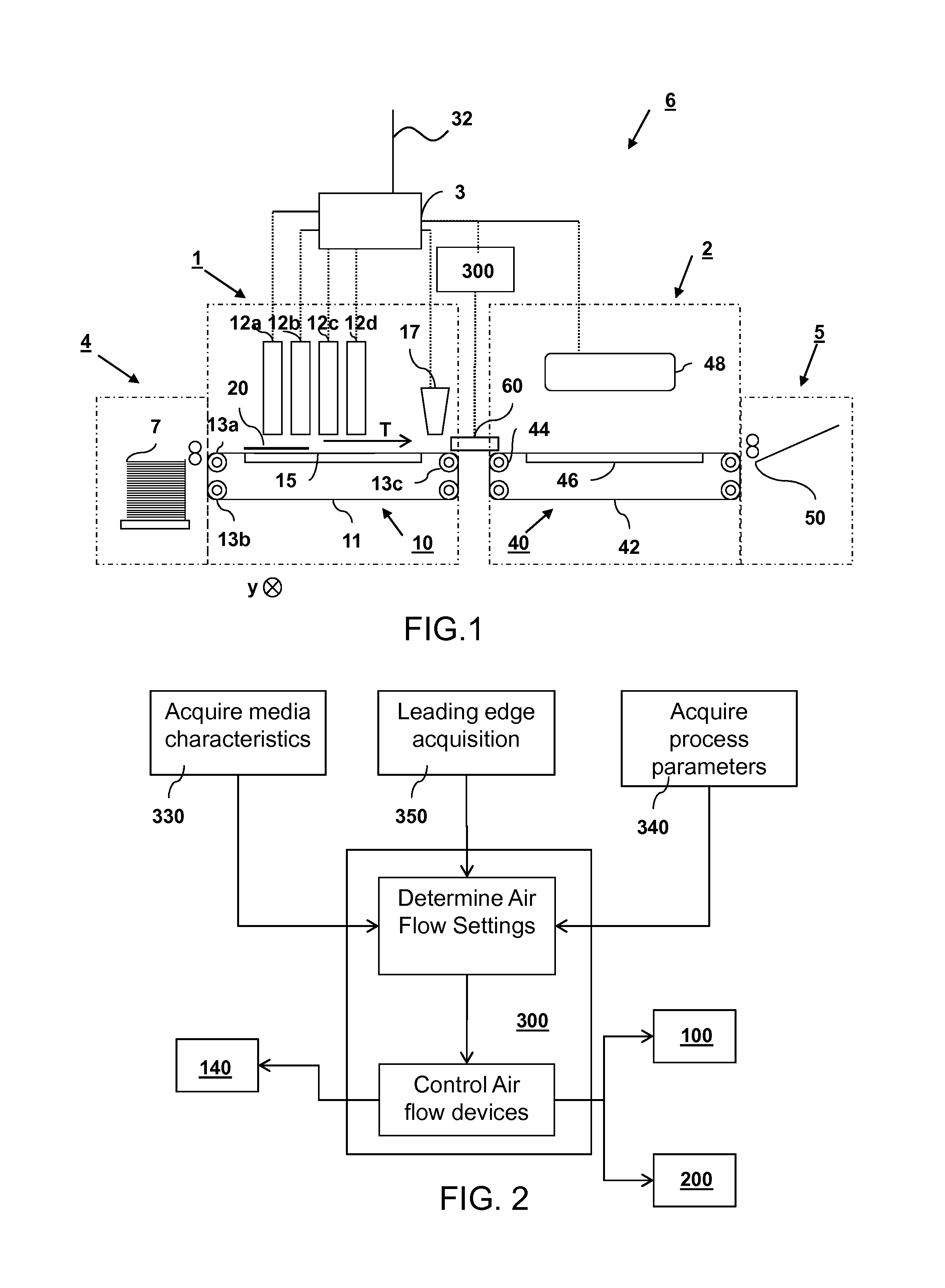
[0048]In FIG. 1 an inkjet printing system 6 is shown. The inkjet printing system 6 comprises an inkjet marking module 1, an inkjet print drying module 2 and a data controller 3. The controller is connected to a network through a network cable 32. The print data enters the controller through the network and is further processed. The print data can be saved on a non-volatile memory like a hard disk and sent to the inkjet marking module 1 using an interface board (not shown).

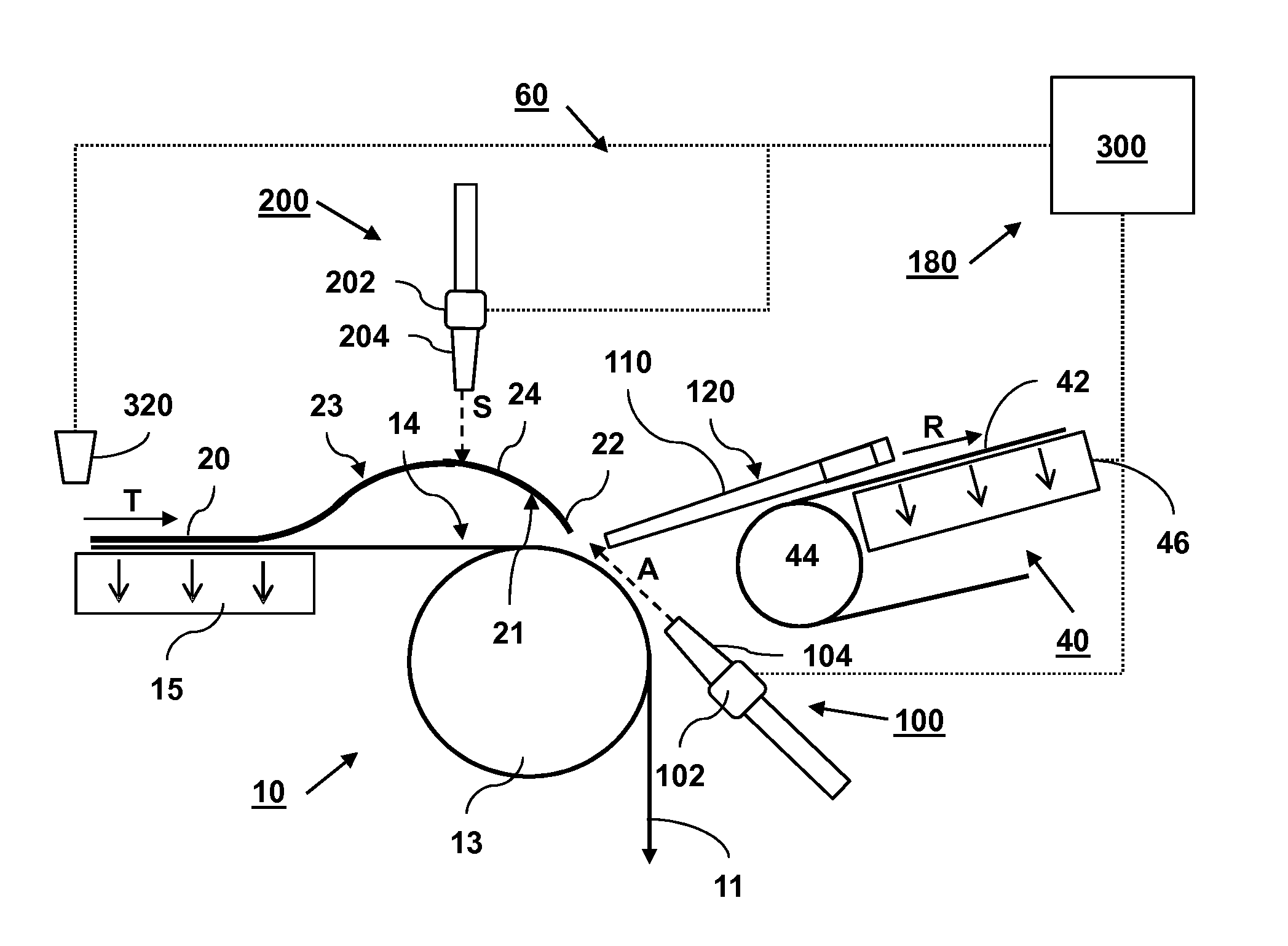
[0049]A cut sheet supply module 4 supplies a receiving medium 20 to the inkjet marking module 1. In the cut sheet supply module 4 the receiving medium is separated from a pile 7 and brought in contact with the transport belt 11 of the supplying conveyor 10 of the inkjet marking module 1. The supplying c...


PUM

PropertyMeasurementUnit
Flow rateaaaaaaaaaa
Stiffnessaaaaaaaaaa
Deformation enthalpyaaaaaaaaaa

Abstract

A method is provided for transferring a sheet in a sheet transport assembly from a supplying conveyor to a receiving conveyor. The method comprises the steps of: arranging a contact side of a sheet in contact with a transport belt of the supplying conveyor; advancing the sheet on the transport belt in a transport direction along a process unit, which is arranged for applying a process to a process side of the sheet, the process side being opposite to the contact side, to a transfer area where the sheet is transferred to a receiving conveyor; controlling an air flow directed onto the process side of sheet for urging the sheet towards a supporting element, which supports the sheet during transport in the transfer area, thereby correcting a curl deformation of the sheet. The air flow is controlled in response to at least one sheet attribute comprising a media characteristic of the sheet, wherein said media characteristic defines a curl deformation behavior of the sheet.

Description

FIELD OF THE INVENTION[0001]The present invention relates to a method for transferring a sheet between two conveyors. The present invention further relates to a sheet transport assembly for transferring a sheet between two conveyors. The present invention further relates to an inkjet printing apparatus comprising the sheet transport assembly according to according to the present invention.BACKGROUND ART[0002]A known inkjet printing apparatus comprises two conveyors, one supplying a sheet of paper or other material, to a transfer area and one receiving the sheet after being transferred from the supplying conveyor. The supplying conveyor, such as a print belt conveyor having a transport belt for advancing the sheet along an inkjet print station, is arranged for advancing the sheet in a transport direction to a transfer area where the sheet is transferred to the receiving conveyor. Said print station may be arranged for applying an inkjet image onto a process side of the sheet using an...

Claims


Application Information

Patent Timeline
IPC IPC(8): B41J11/00B65H5/02B65H7/16
CPCB41J11/0005B65H5/021B65H7/16B65H29/242B65H5/224B65H7/06B65H2301/44735B65H2301/51256B65H2404/2691B65H2511/416B65H29/56B65H2406/122B65H2511/16B65H2515/81B65H2557/64B65H2801/15B65H2515/10B65H2515/20B65H2515/34B65H2220/01B65H2220/02B65H2220/03
Inventor LA VOS, PETER G.DINNISSEN, JOHANNES H.A.KAWAGUCHI, DAISUKE
Owner OCE TECH
Why Eureka
Try Eureka