Aerospace plane system

a technology for space planes and aircraft, applied in the field of space planes, can solve the problems of reducing aircraft range and payload capacity for a given fuel load, affecting the flight of aircraft, and affecting the flight of aircraft, and achieve the effect of successful engine relighting

Active Publication Date: 2016-06-02
COMML AEROSPACE PLANE PTY
View PDF17 Cites 23 Cited by
  • Summary
  • Abstract
  • Description
  • Claims
  • Application Information

AI Technical Summary

Benefits of technology

[0031]Desirably, the pressure doors include a front engine pressure door and an aft engine pressure door to prevent engine cold soak and achieve successful engine relight, whereby the front engine pressure door swings forward and is held

Problems solved by technology

Currently a net downward balancing force is created by a horizontal stabilizer resulting in ‘induced and trim’ drag reducing aerodynamic efficiencies.
This significantly reduces aircraft range and payload capacity for a given fuel load.
The McDonnell MD-11 for example, was designed as a relaxed stability airplane and some jet upsets (unusual flight attitudes) resulted.
Jet upsets are extremely undesirable and it is therefore important to both design flight control software and flight control surfaces with suffic

Method used


Image

  • Aerospace plane system
  • Aerospace plane system
  • Aerospace plane system

Examples


Embodiment Construction

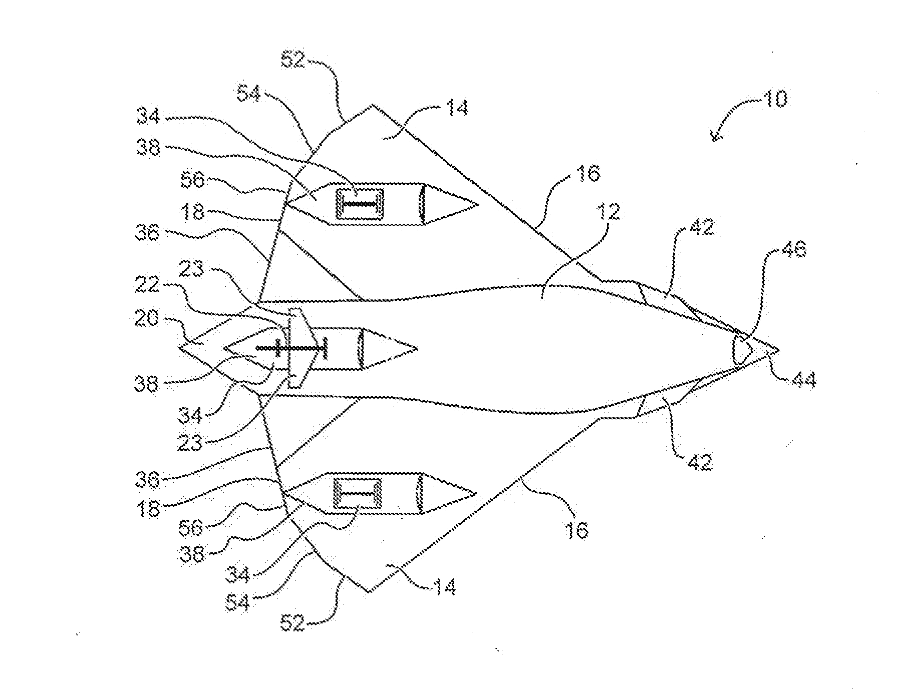
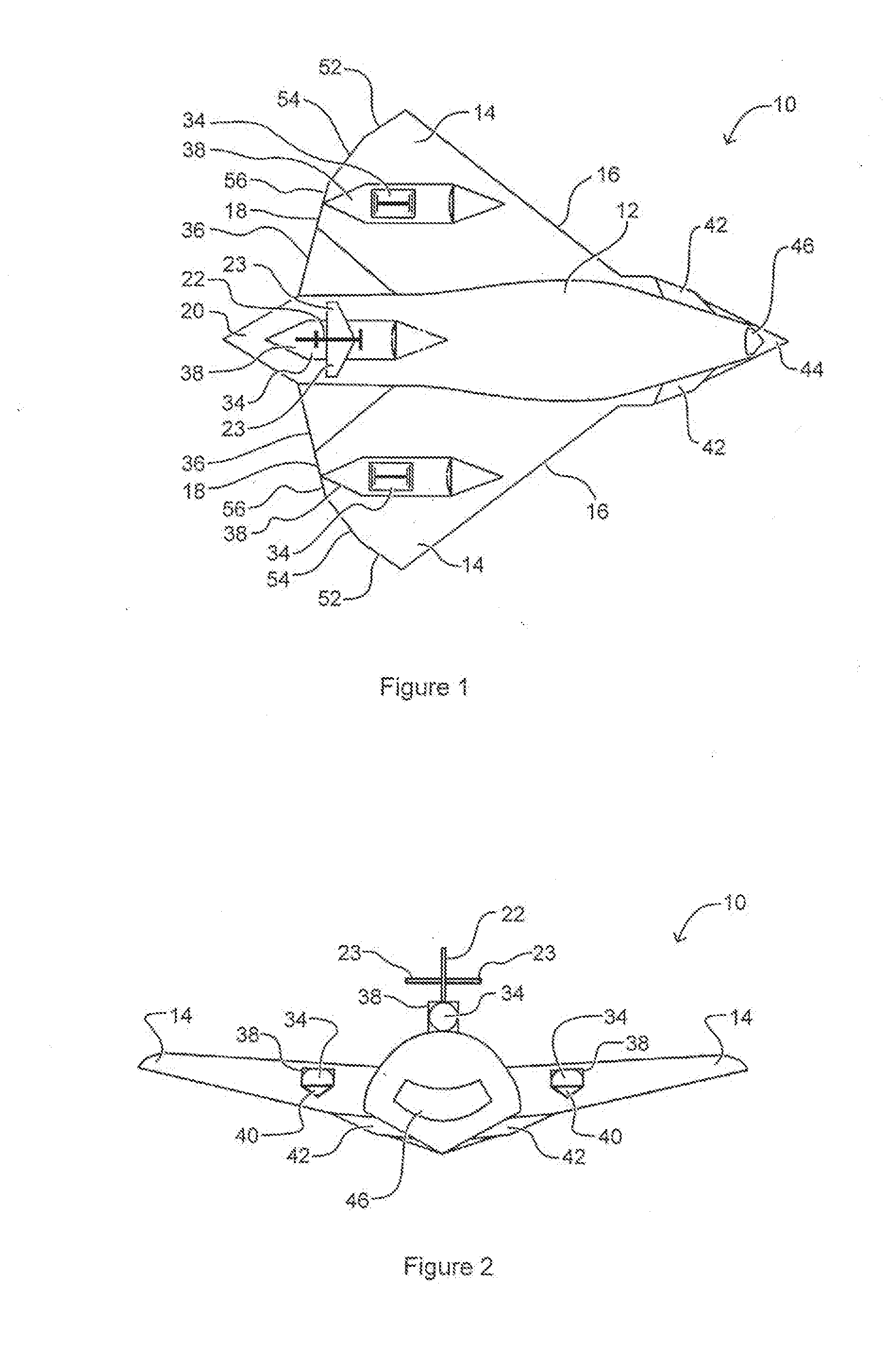
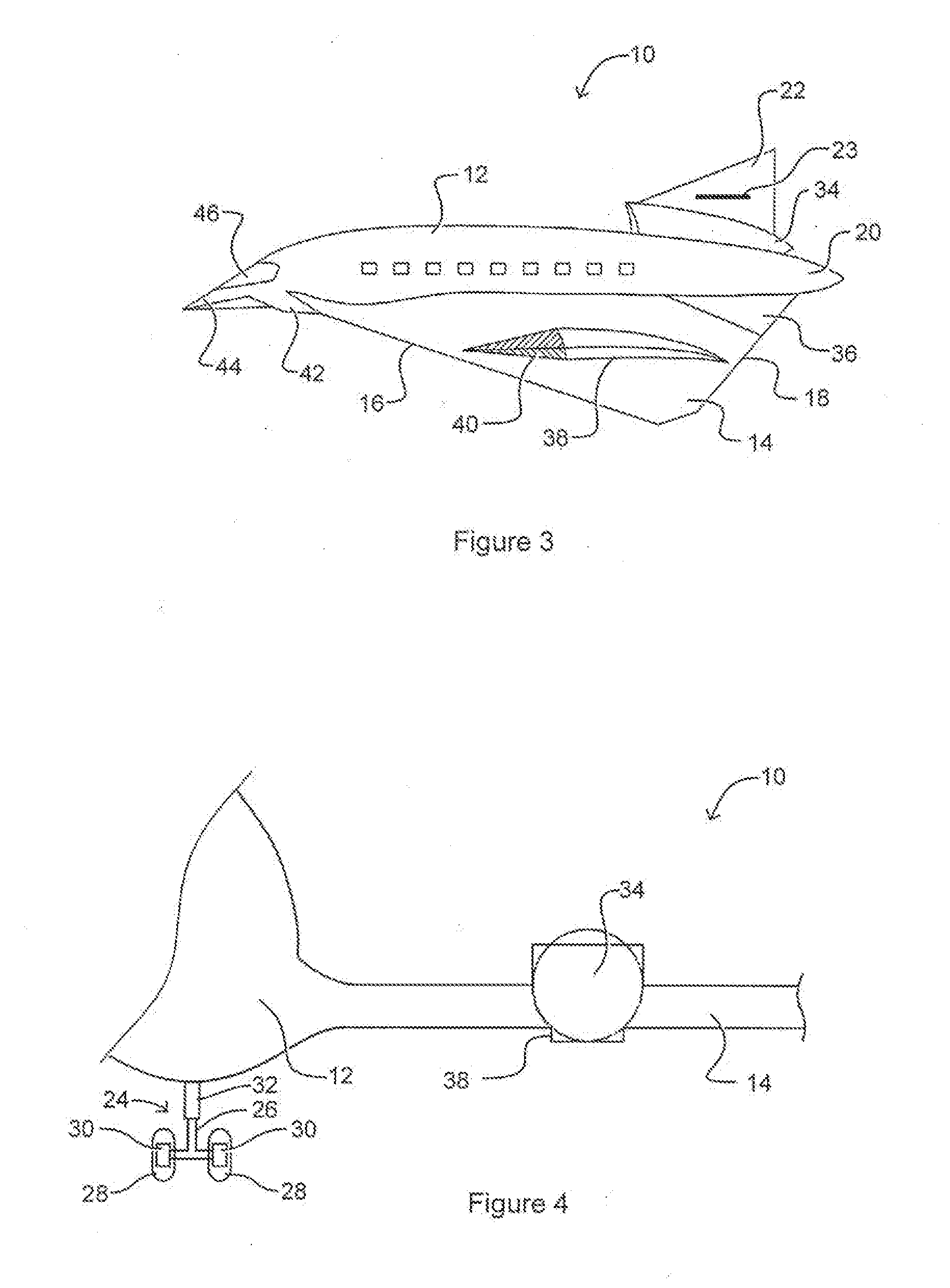
[0041]Referring to FIG. 1, an aerospace plane 10 has an elongate body 12 supporting a pair of wings 14, 14. Each of the pair of wings 14, 14 has a leading edge 16 and a trailing edge 18. The pair of wings 14, 14 is adapted to extend away from the elongated body 12 in opposing directions. The pair of wings 14, 14 have an approximate triangular shape with the hypotenuse of each wing 14, 14 aligned essentially parallel with the elongated body 12. Each of the pair of wings 14, 14 is a mirror image of one another. Each of the pair of wings 14, 14 angle backward and outward from the elongated body 12. The elongated body 12 has a rear end 20 and a tail 22. Each of the pair of wings 14, 14 is widest as it approaches the tail 22. The tail 22 extends upward from the elongated body 12 approximate the rear end 20. The tail 22 also extends away from a rear end 20 of the elongated body 12. The tail 22 can include at least one stabilizer 23. A pair of stabilizers 23, 23 is depicted in FIGS. 1 and ...


PUM


Abstract

An aerospace plane having an elongate body supporting a pair of wings each having at least two angled, trailing edge portions. The pair of wings are adapted to extend away from the elongated body in opposing directions. A landing gear assembly is operatively associated with the elongated body to be moveable from a retracted position where the landing gear assembly is substantially locatable within the elongated body and an extended position where the landing gear assembly extends at least partially away from the elongated body. At least one engine adapted to generate thrust. At least one stabilizer adapted to assist with movement of the aerospace plane during flight. The at least one engine is located at least partially within an intake housing adapted to direct air into said at least one engine. The intake housing having at least one inlet door adapted to move from a fully open position, which allows air to pass into the engine, to a sealingly closed position which prevents air from flowing into the engine, when the engine is shut down during flight.

Description

CROSS-REFERENCE TO RELATED APPLICATION[0001]This application claims priority as a Continuation-In-Part application to Regular application U.S. Ser. No. 14 / 390,470 filed Oct. 3, 2014, which claims priority to PCT / AU2013 / 000348 filed Apr. 4, 2013, which in turn claims priority to Australian patent application No. 2012901351 filed Apr. 4, 2012.FIELD OF THE INVENTION[0002]The present invention relates to an aerospace plane and in particular to a commercial aerospace plane system.BACKGROUND OF THE INVENTION[0003]Airplanes are vehicles capable of flight by way of wings that interact with pressure and airflow to generate lift. A wing has an air foil cross sectional shape that generates lift by creating a pressure differential where there is a high pressure below the wing and low pressure above the wing. In this way the pressure differential supports the weight of the aeroplane in flight.[0004]Airplanes have been utilised extensively since the 1950's to transport people and goods about the ...

Claims


Application Information

Patent Timeline
IPC IPC(8): B64C1/26B64C3/32B64C5/08B64C9/00B64D37/34B64C25/34B64C39/12B64D15/06B64D27/18B64C3/10B64C15/02
CPCB64D37/34B64C2039/105B64C1/26B64C3/10B64C3/32B64D27/18B64C9/00B64C15/02B64C25/34B64C39/12B64D15/06B64C5/08B64C30/00B64D31/00B64D2033/022B64D2033/026Y02T50/10Y02T50/40
Inventor ALEXANDER, NICK
Owner COMML AEROSPACE PLANE PTY
Why Eureka
Try Eureka