Vehicle comprising an electrical storage device cooled by a fan

a technology of electrical storage device and passenger compartment, which is applied in the direction of battery/fuel cell control arrangement, transportation and packaging, etc., can solve the problem of passenger compartment strangeness and reduce the air quantity of the fan, and achieve the effect of easy suppression of air flow

Active Publication Date: 2016-06-09
TOYOTA JIDOSHA KK
View PDF18 Cites 8 Cited by
  • Summary
  • Abstract
  • Description
  • Claims
  • Application Information

AI Technical Summary

Benefits of technology

[0025]In the fourth aspect of the invention, the temperature difference between the passenger compartment and the discharge chamber is identified, and the fan is driven at the air quantity smaller than the reference air quantity when the temperature difference is larger than or equal to the predetermined difference. Thus, as in the case of the second aspect of the invention, it is possible to bring the temperature of the discharge chamber close to the temperature of the passenger compartment by decreasing the temperature of the discharge chamber while suppressing a situation that air is pushed out from the discharge chamber to the passenger compartment.
[0026]In the...

Problems solved by technology

If the temperature of the boot is different from the temperature of the passenger compartment, a passenger in the pass...

Method used


Image

  • Vehicle comprising an electrical storage device cooled by a fan
  • Vehicle comprising an electrical storage device cooled by a fan
  • Vehicle comprising an electrical storage device cooled by a fan

Examples


first embodiment

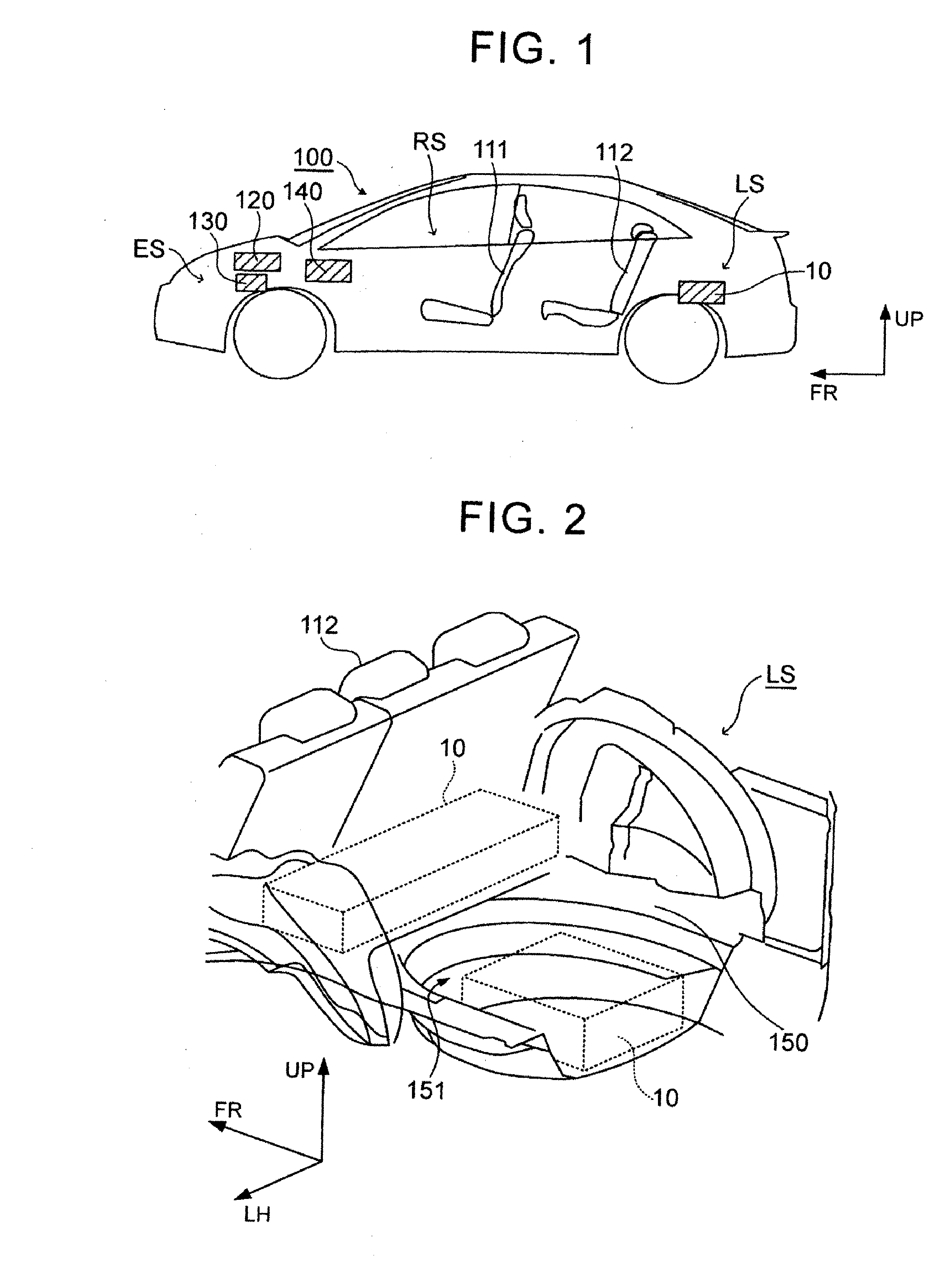
[0044]A vehicle will be described with reference to FIG. 1 and FIG. 2. FIG. 1 is a schematic view that shows the configuration of the vehicle. FIG. 2 is a schematic view that shows the configuration of part of the vehicle. In FIG. 1 and FIG. 2, the arrow FR indicates a direction in which the vehicle 100 travels forward, and the arrow UP indicates an upward direction of the vehicle 100. In FIG. 2, the arrow LH indicates a leftward direction when oriented in the forward direction FR of the vehicle 100.

[0045]The vehicle 100 includes a passenger compartment RS, a luggage compartment LS and an engine compartment ES. The passenger compartment RS is a space in which a passenger is seated. Seats 111, 112 are arranged in the passenger compartment RS. The passenger compartment RS and the engine compartment ES are partitioned from each other by a dashboard provided in the vehicle 100.

[0046]The luggage compartment LS is a space in which a luggage, or the like, is arranged. The luggage compartm...

second embodiment

[0144]The temperature difference ΔT may be calculated as in the case of the Specifically, the temperature set in the air-conditioning system 140 may be treated as the temperature of the passenger compartment RS. The outside air temperature Tout may be treated as the temperature of the spaces S1, S2, S3. Thus, a difference between the setting temperature in the air-conditioning system 140 and the outside air temperature Tout may be estimated as the temperature difference ΔT.

[0145]On the other hand, both the temperature of the passenger compartment RS and the temperature of the spaces S1, S2, S3 may be detected, and the temperature difference ΔT may be calculated on the basis of these detected results. In this case, a temperature sensor for detecting the temperature of the passenger compartment RS and a temperature sensor for detecting the temperature of the spaces S1, S2, S3 just need to be provided. When the temperature of the spaces S1, S2, S3 is treated as the outside air tempera...


PUM


Abstract

When a device temperature (Tb) of an electrical storage device (10) is higher than or equal to a reference temperature, a fan (22) is driven at an air quantity larger than or equal to a reference air quantity. On the other hand, when the device temperature is lower than the reference temperature, air that has received heat from the electrical storage device is guided to a discharge chamber by driving the fan at an air quantity smaller than the reference air quantity on the basis of the fact that an air-conditioning system is operating and an outside air temperature is lower than or equal to a predetermined temperature. When the air-conditioning system is operating and the outside air temperature is lower than or equal to the predetermined temperature, it is assumed that there is a temperature difference between a passenger compartment and the discharge chamber. At this time, by driving the fan at the air quantity smaller than the reference air quantity, it is possible to bring the temperature of the discharge chamber close to the temperature of the passenger compartment by raising the temperature of the discharge chamber, so it is possible to reduce the temperature difference between the discharge chamber and the passenger compartment.

Description

BACKGROUND OF THE INVENTION[0001]1. Field of the Invention[0002]The invention relates to a vehicle including a system that adjusts the temperature of an electrical storage device by supplying air to the electrical storage device.[0003]2. Description of Related Art[0004]In Japanese Patent Application Publication No. 2013-001382 (JP 2013-001382 A), a battery pack is cooled by supplying air in a cabin of a vehicle to the battery pack. Here, air after cooling the battery pack is discharged to a boot.SUMMARY OF THE INVENTION[0005]Depending on a vehicle, a space in which a passenger is seated (hereinafter, referred to as passenger compartment) and a boot communicate with each other, and air is allowed to move between the passenger compartment and the boot. Even in a vehicle in which a passenger compartment and a boot are partitioned from each other, a gap may occur at a portion that partitions the passenger compartment and the boot from each other, and air may move between the passenger c...

Claims


Application Information

Patent Timeline
IPC IPC(8): B60H1/00B60L11/18B60H1/14
CPCB60H1/00278B60H1/00392B60L11/1874B60H1/143B60H1/00885B60H1/00828B60H2001/003B60L1/003B60L7/14B60L2240/34B60L2240/36B60L2240/545B60L50/51B60L58/21B60L58/26B60L50/66Y02E60/10B60H1/00Y02T10/70
Inventor MINAMIURA, KEIICHIKIKUCHI, YOSHIAKI
Owner TOYOTA JIDOSHA KK
Why Eureka
Try Eureka