Rear vehicle-body structure of automotive vehicle

a rear vehicle and body technology, applied in the direction of roofs, vehicle arrangements, transportation and packaging, etc., can solve the problems of rear side frame bucking performance deterioration, improper peeling of welding parts, rear side frame breaking or improper peeling, etc., to achieve the effect of reducing the risk of damage, and reducing the service life of the rear side fram

Active Publication Date: 2016-06-09
MAZDA MOTOR CORP
View PDF2 Cites 11 Cited by
  • Summary
  • Abstract
  • Description
  • Claims
  • Application Information

AI Technical Summary

Benefits of technology

[0009]An object of the present invention is to provide a rear vehicle-body structure of an automotive vehicle which can properly absorb the collisio

Problems solved by technology

In recent years, reducing of the weight and thickness of the rear side frame has been attained by using a high-tensile steel plate, so that the bucking performance of the rear side frame deteriorates because of the thin plate-thickness and also breaking of the rear side frame or peeling of a welding portion improperly occur because of the high tension.
Consequently, it has become difficult to control load-absorption and deformation of the rear side fra

Method used


Image

  • Rear vehicle-body structure of automotive vehicle
  • Rear vehicle-body structure of automotive vehicle
  • Rear vehicle-body structure of automotive vehicle

Examples


Embodiment Construction

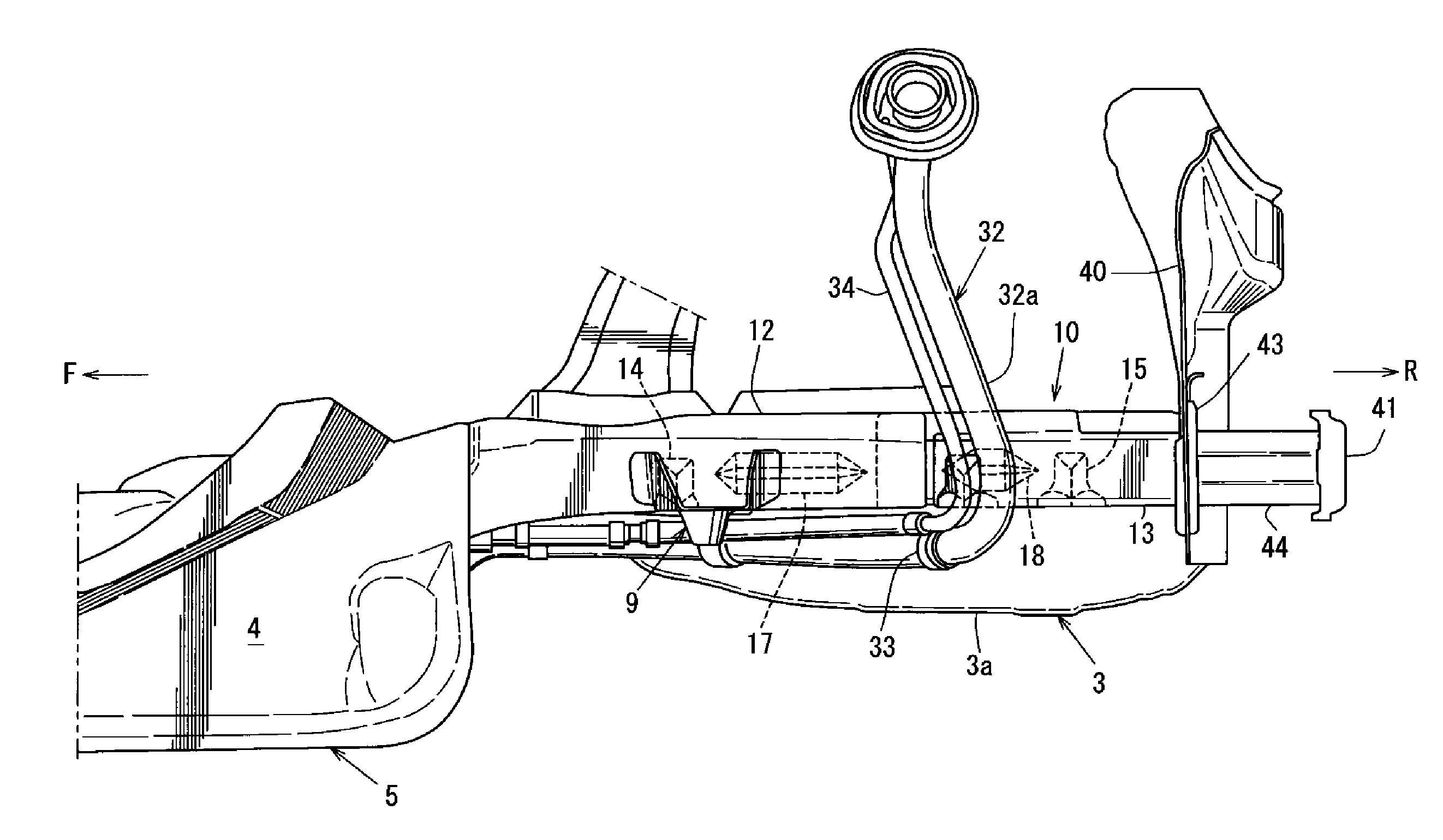
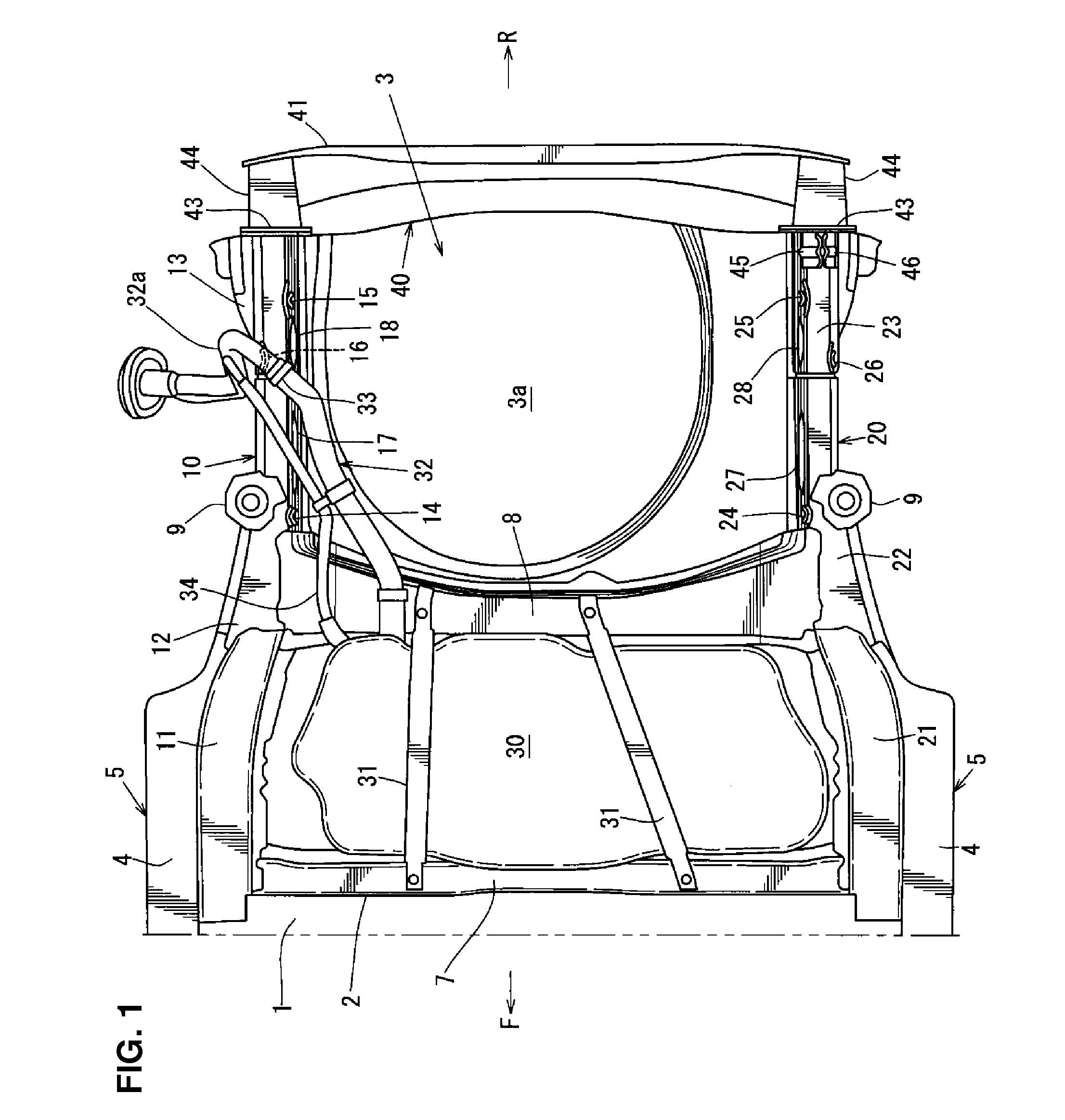
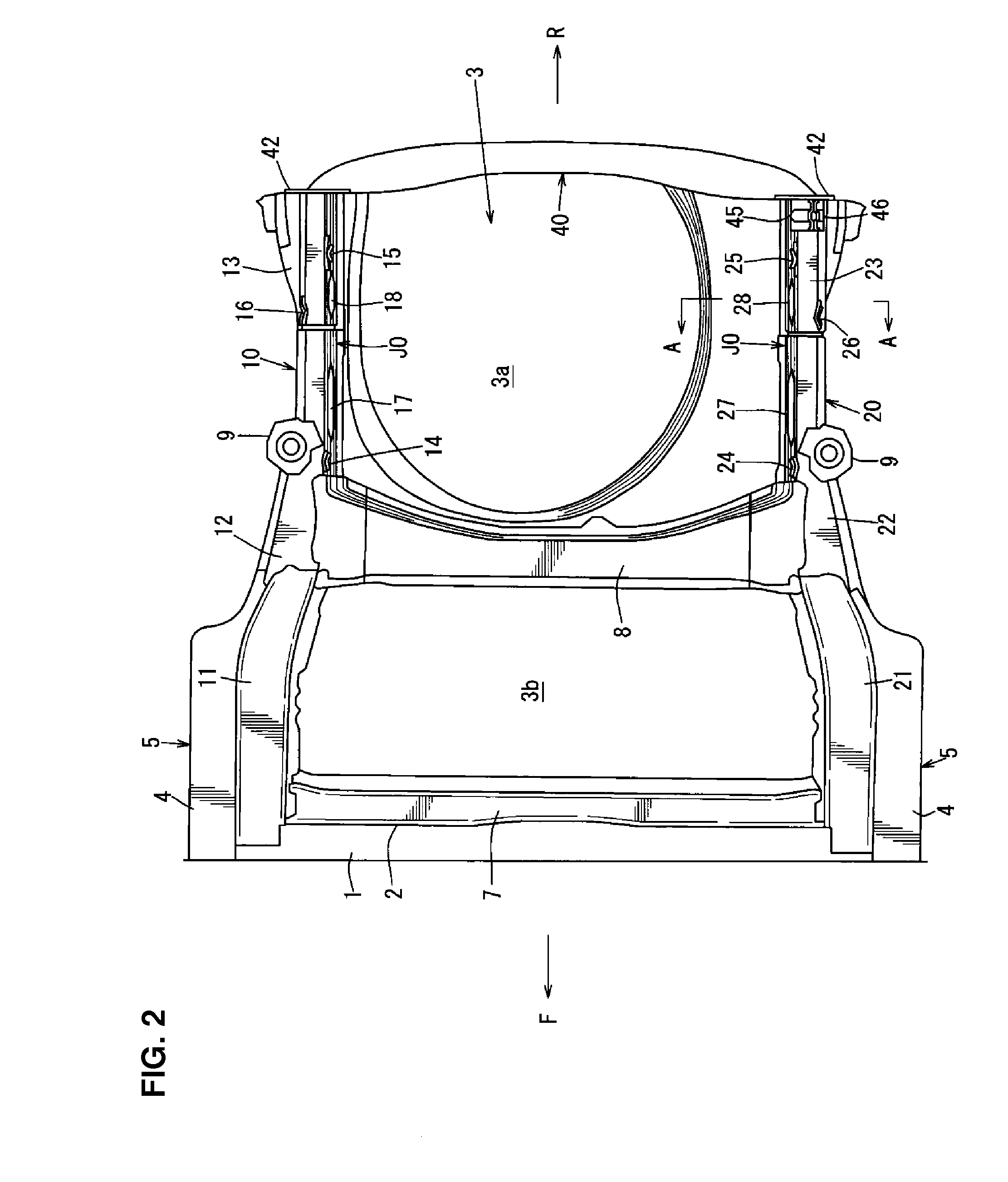
[0030]Hereafter, an embodiment of the present invention will be described referring to the drawings. The drawings show a rear vehicle-body structure of an automotive vehicle. FIG. 1 is a bottom view showing a rear vehicle-body structure of an automotive vehicle of the present invention, FIG. 2 is a bottom view showing a state in which a fuel tank, a fuel feeding pipe, and a breather pipe are removed from the structure shown in FIG. 1, FIG. 3 is a plan view showing a major part of a left side of the rear vehicle-body structure of the automotive vehicle, and FIG. 4 is a side view of FIG. 3.

[0031]In FIGS. 1 and 2, a floor panel 1 which forms a floor face of a vehicle compartment is provided, and a rear floor panel 3 is continuously and integrally provided behind the floor panel 1 via a kick-up portion 2 which rises upward. A recess portion 3a which also serves as a spare tire pan is formed at a central position, in a vehicle width direction, of a rear part of the rear floor panel 3. A ...


PUM


Abstract

A pair of rear side frames respectively comprise front bending-promotion portions, middle bending-promotion portions and rear bending-promotion portions which cause the rear side frames to bend inward, in a vehicle width direction, in a trough-folding shape in a rear collision of a vehicle, and a longitudinal distance L2 between the front bending-promotion portions and the middle bending-promotion portions is set to be longer than a longitudinal direction L1 between the middle bending-promotion portions and the rear bending-promotion portions. Thereby, there is provided a rear vehicle-body structure of an automotive vehicle which can properly absorb a collision load at a vehicle-body rear portion, even if a rear side frame is made from material which may not cause smooth bucking of the rear side frame.

Description

BACKGROUND OF THE INVENTION[0001]The present invention relates to a rear vehicle-body structure of an automotive vehicle which comprises a rear floor panel and a pair of right-and-left rear side frames extending in a vehicle longitudinal direction and connected to both side portions, in a vehicle width direction, of the rear floor panel.[0002]Generally, a pair of right-and-left rear side frames which extend in a vehicle longitudinal direction are provided at a rear vehicle-body portion of an automotive vehicle for the purpose of ensuring the vehicle-body rigidity.[0003]In recent years, reducing of the weight and thickness of the rear side frame has been attained by using a high-tensile steel plate, so that the bucking performance of the rear side frame deteriorates because of the thin plate-thickness and also breaking of the rear side frame or peeling of a welding portion improperly occur because of the high tension. Consequently, it has become difficult to control load-absorption a...

Claims


Application Information

Patent Timeline
IPC IPC(8): B62D21/15B62D25/08
CPCB62D25/08B62D21/152B62D25/087
Inventor MATSUOKA, HIDENORIYAMADA, KENMASUDA, AKIYOSHIMATSUSHITA, KOUJI
Owner MAZDA MOTOR CORP
Why Eureka
Try Eureka