Energy storage tank having function of fixing energy storage units

a technology of energy storage tank and function, which is applied in the field of energy storage structure, can solve the problems of low cold amount of ice balls, smaller density of ice balls than that of working liquids, etc., and achieve the effect of improving energy storage efficiency of energy storage tanks

Inactive Publication Date: 2016-06-09
KUNSHAN JUZHONG ELECTRONICS
View PDF23 Cites 4 Cited by
  • Summary
  • Abstract
  • Description
  • Claims
  • Application Information

AI Technical Summary

Benefits of technology

[0007]One objective of the present invention is to provide an energy storage tank having a function of fixing energy storage units, which uses installation parts and fixing parts to hold the energy storage units completely in the working liquid such that the energy storage units are fixed in the tank body in series or by group

Problems solved by technology

However, the biggest problem regarding the scattered ice balls is that the density of the ice ball is smaller than that of the working liquid.
Besides, a large amount of the ice balls causes accumulation and part of the ice balls will float on the working liquid.
As a result, the

Method used


Image

  • Energy storage tank having function of fixing energy storage units
  • Energy storage tank having function of fixing energy storage units
  • Energy storage tank having function of fixing energy storage units

Examples


first embodiment

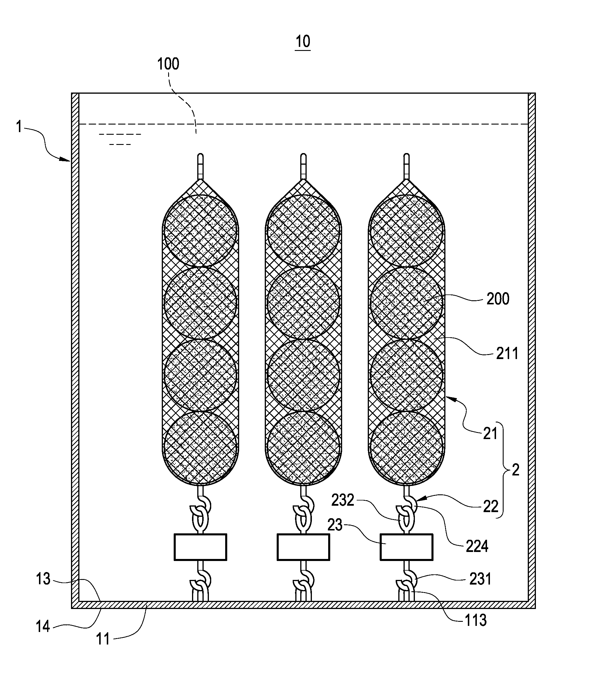
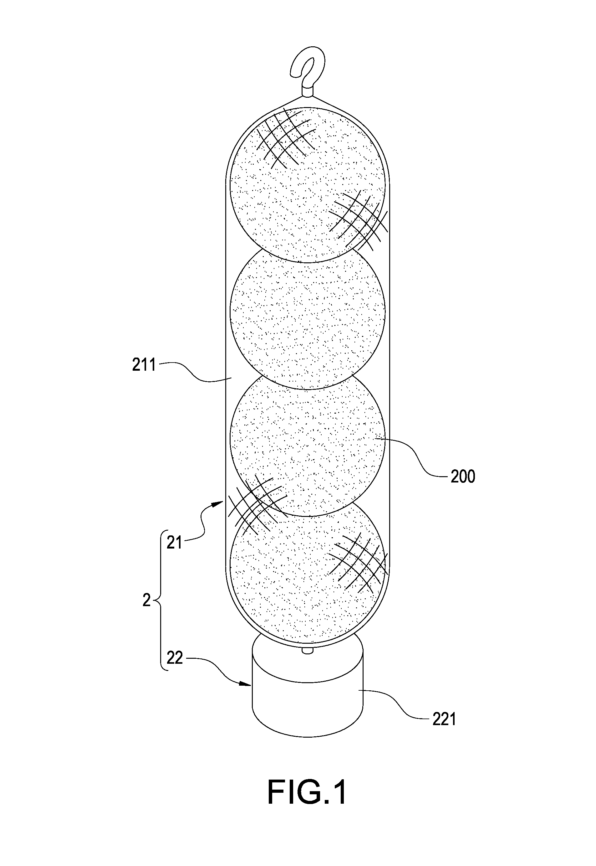
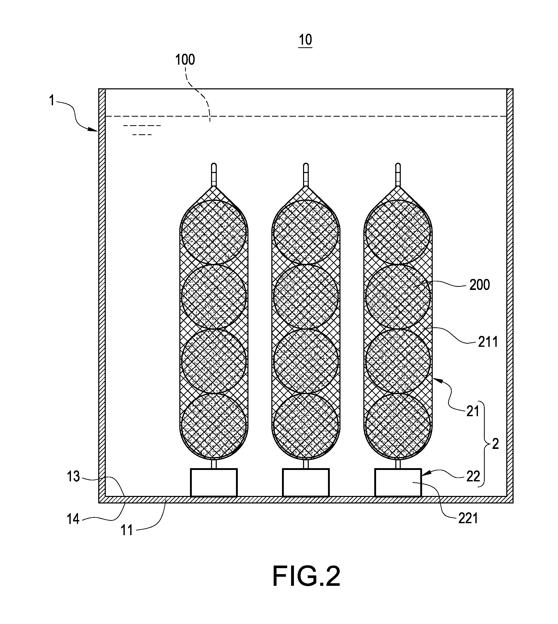
[0029]The detailed description is given below. The magnets 111 are install on the internal side surface 13 of the bottom plate 11. The installation part 22 is a magnetic part 222 made of a material containing iron. The magnet 111 and the magnetic part 222 attract to each other. In this way, through the magnetic attraction between the magnet 111 and the magnetic part 222, the magnetic part 222 is fixed to the bottom plate 11 such that the bag 211 and the energy storage units 200 are completely held under the surface of the working liquid 100, achieving the same function and effect as the

[0030]Please refer to FIG. 4, which shows the energy storage tank 10 according to the third embodiment of the present invention. The third embodiment is roughly similar to the second embodiment. The difference is that the magnets 111 are installed on the external side surface 14 in the third embodiment.

second embodiment

[0031]The detailed description is given below. The magnets 111 are installed either on the internal side surface 13 or on the external side surface 14; either of the above two cases will make the magnetic parts 222 be fixed steadily to the bottom plate 11 to achieve the same function and effect as the

[0032]Please refer to FIG. 5, which is the fourth embodiment of the present invention. The fourth embodiment is roughly similar to the first embodiment. The difference is that the bottom plate 11 is provided with plural magnetic parts 112 in the fourth embodiment.

[0033]A further explanation is given below. The bottom plate 11 is made of a material containing iron such that the bottom plate 11 itself is a magnetic part 112. The installation part 22 is a magnet 223. The magnet 223 and the magnetic part 112 attract to each other. In this way, through the magnetic attraction between the magnet 223 and the magnetic part 112, the magnet 223 is fixed to the bottom plate 11 such that the bag 21...

sixth embodiment

[0041]The detailed description is given below. As shown in FIG. 7, the first hook 113 has a roughly U-like shape and the second hook 224 has a roughly C-like shape. The U-like hook and the C-like hook hook to each other. As shown in FIG. 8, the first hook 113 has a roughly C-like shape and the second hook 224 has a roughly O-like shape. The C-like hook and the O-like hook can also hook to each other, achieving the same function and effect as the However, the fixing assembly 2 is apt to sway in the working liquid 100. The hook which has a U-like or O-like shape can prevent the two attached hooks from swaying and separating from each other to enhance the hooking stability.

[0042]Similarly, both of the first hook 113 and the second hook 224 can have a C-like shape. These two C-like hooks can hook to each other to achieve the same function and effect as the sixth embodiment.

[0043]Please refer to FIG. 9, which is the eighth embodiment of the present invention. The eighth embodiment is ro...


PUM


Abstract

An energy storage tank having a function of fixing energy storage units used for a working liquid includes a fixing assembly and a tank body that is for filling of the working liquid and has a bottom plate. The fixing assembly is received in the tank body and includes a fixing part to which the energy storage units are connected and an installation part that is fixed at the fixing part and disposed on the bottom plate. The installation part and the fixing part hold the energy storage units completely in the working liquid. Therefore, the energy storage units are fixed in the tank body in series or by group and distributed evenly in the working liquid such that each of the energy storage units can completely contact the working liquid to enhance energy storage efficiency of the energy storage tank.

Description

BACKGROUND OF THE INVENTION[0001]1. Field of the Invention[0002]The present invention relates to an energy storage structure containing a cold storage liquid or a heat storage liquid and, in particular, to an energy storage tank having a function of fixing energy storage units.[0003]2. Description of Related Art[0004]In general, an energy storage air-conditioning system has a tank body which contains a working liquid for freezing or heating and several energy storage units. The energy storage units are scattered in the tank body. For example, ice balls are commonly used to be put in the cold storage tank.[0005]However, the biggest problem regarding the scattered ice balls is that the density of the ice ball is smaller than that of the working liquid. Besides, a large amount of the ice balls causes accumulation and part of the ice balls will float on the working liquid. As a result, the ice balls in the upper layer of the working liquid may not be frozen and the cold storage amount i...

Claims


Application Information

Patent Timeline
IPC IPC(8): F24F5/00F25D3/04
CPCF24F5/0021F24F2005/0025F25D3/045F24F5/0017F28D20/00F28D20/0034F28D20/02F28D2020/0021F28F2275/22Y02E60/14
Inventor KUO, DAH-CHYIWANG, APPLELONG, LINGXIA, TONG-HU
Owner KUNSHAN JUZHONG ELECTRONICS
Why Eureka
Try Eureka