
Catalyst deterioration diagnosis system and catalyst deterioration diagnosis method

a technology of catalytic ability and diagnosis system, which is applied in the direction of electrical control, exhaust treatment, electrical control, etc., can solve the problems of deterioration of fuel economy, inability to apply diagnosis to the diagnosis of the capability to convert (oxidize or combust) unburned hydrocarbons, and inability to avoid deterioration of fuel economy. , to achieve the effect of excellent accuracy, degree of deterioration of catalytic ability, and accurate diagnosis of degree degr

Inactive Publication Date: 2016-06-09
NGK INSULATORS LTD
View PDF1 Cites 2 Cited by
  • Summary
  • Abstract
  • Description
  • Claims
  • Application Information

AI Technical Summary

Benefits of technology

The present invention provides a method to accurately diagnose the deterioration of an oxidation catalyst in real-time, using a hydrocarbon gas sensor. This helps to ensure the engine system operates efficiently and reduces emissions.

Problems solved by technology

However, there is a problem that as disclosed in Japanese Patent Application
However, in such a method, there is a problem that error cause due to changes in an exhaust gas temperature and exhaust gas flow rate in actual use is too large, and a problem that a fuel injection amount for accelerating heat generation is large and therefore deterioration of fuel economy cannot be avoided.
That is, this means that in order to diagnose the deterioration of an oxidation catalyst by use of the air-fuel ratio sensor or the oxygen sensor, it is necessary to calculate, with accuracy, Δλ or a difference in electromotive force which corresponds to a change in an oxygen consumption of ppm order, but measurement accuracy of such an extent cannot be attained in the first place in the air-fuel ratio sensor and the oxygen sensor.
However, even though capability to oxidize NO of the oxidation catalyst can be diagnosed by such a technique, the result of such diagnosis cannot be applied to the diagnosis of the capability to convert (oxidize or combust) unburned hydrocarbon.
However, in such a method, the diagnosis is only performed based on estimated values, and there is a problem that an influence of error of a signal from each sensor cannot be avoided and the diagnosis accuracy is low.
Japanese Patent Application Laid-Open No. 07-103039 (1995) does not disclose diagnosis of an oxidation catalyst in the diesel exhaust gas in an O2-excessive state at all.

Method used


Image

  • Catalyst deterioration diagnosis system and catalyst deterioration diagnosis method
  • Catalyst deterioration diagnosis system and catalyst deterioration diagnosis method
  • Catalyst deterioration diagnosis system and catalyst deterioration diagnosis method

Examples


first preferred embodiment

[0043]

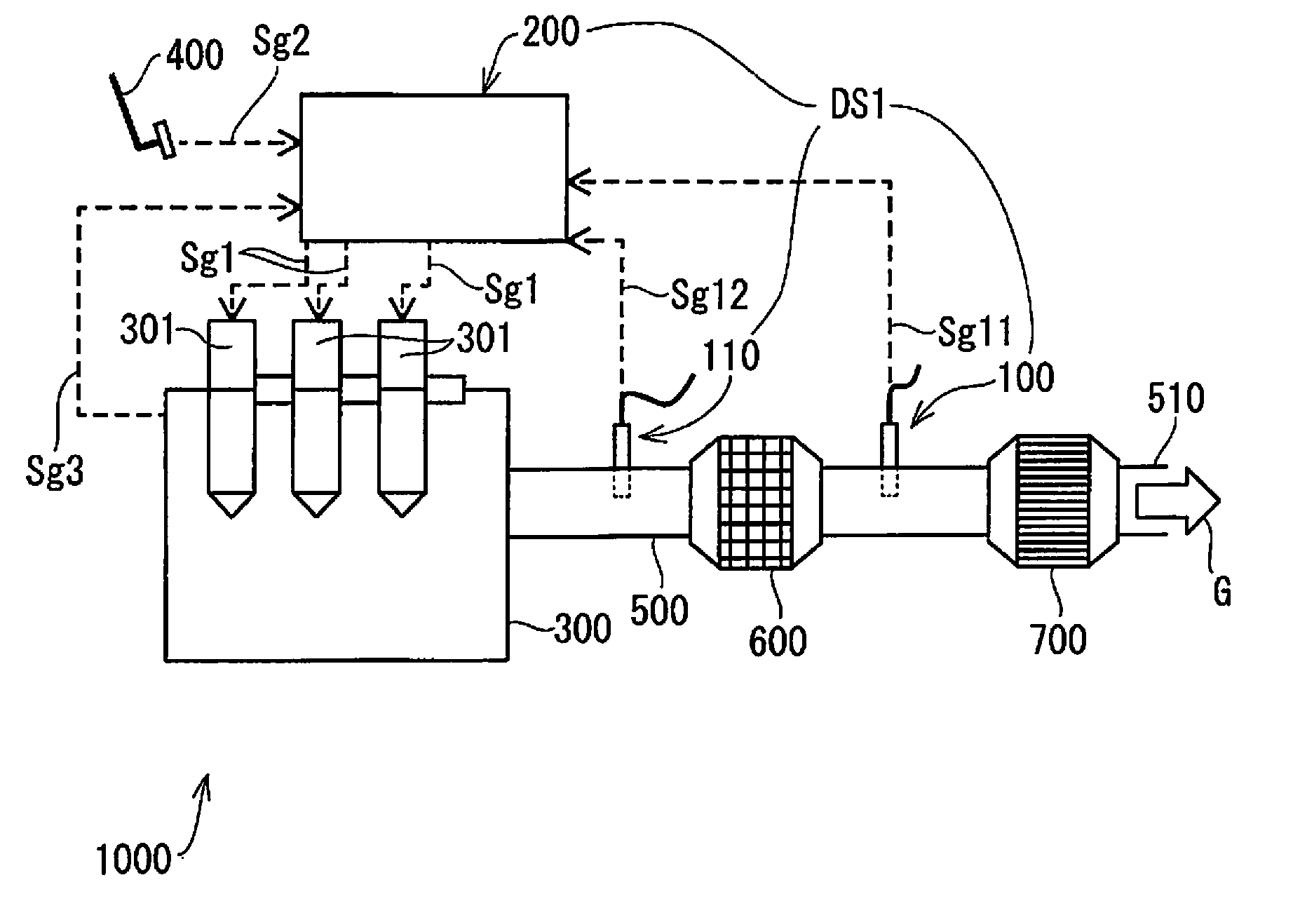
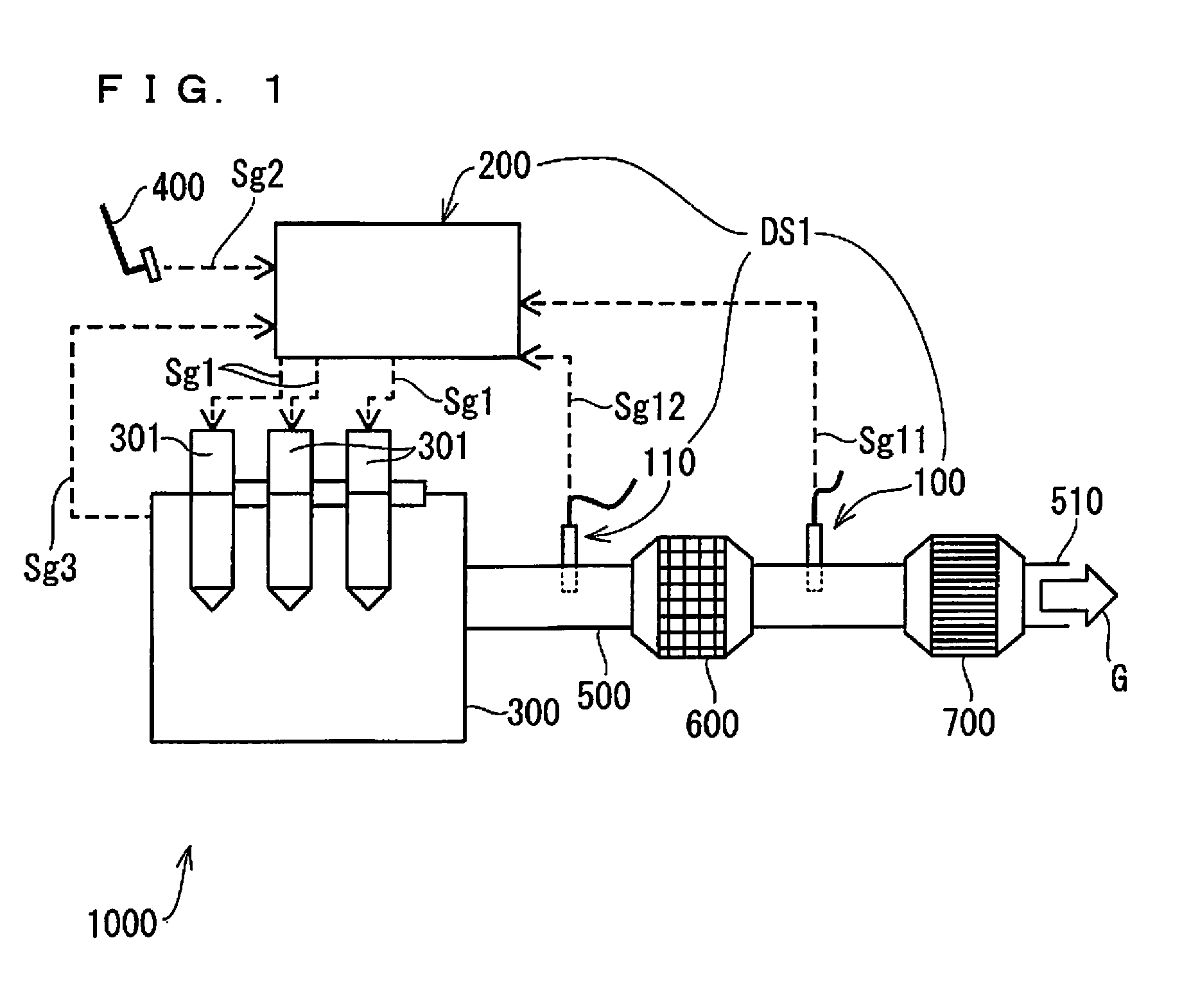
[0044]FIG. 1 is a view schematically showing a schematic configuration of a diesel engine system (hereinafter, also referred to simply as an engine system) 1000 configured to include an oxidation catalyst diagnosis system DS1 of first preferred embodiment of the present invention.

[0045]The oxidation catalyst diagnosis system DS1 mainly comprises a hydrocarbon gas sensor (hereinafter, also referred to as a HC sensor) 100, a temperature sensor 110, and an electronic control device 200 being a control device which controls an operation of the whole engine system 1000.

[0046]The engine system 1000 mainly includes, in addition to the oxidation catalyst diagnosis system DS1, an engine main body 300 being a diesel engine as a type of internal combustion engine, a plurality of fuel injection valves 301 which inject fuel to the engine main body 300, a fuel-injection instructing part 400 for instructing the fuel injection valve 301 to inject fuel, an exhaust pipe 500 forming an exhaust p...

second preferred embodiment

[0186]In the oxidation catalyst diagnosis system DS1 of the above-mentioned first preferred embodiment, the degree of deterioration of the oxidation catalyst 600 is diagnosed without actually calculating the conversion rate; however, in the preferred embodiment, an aspect in which the degree of deterioration of the oxidation catalyst 600 is diagnosed by actually calculating the conversion rate, will be described.

[0187]FIG. 19 is a view schematically showing a schematic configuration of an engine system 2000 configured to include an oxidation catalyst diagnosis system DS2 of second preferred embodiment of the present invention.

[0188]The oxidation catalyst diagnosis system DS2 of the preferred embodiment and the engine system 2000 have the same configurations as in the oxidation catalyst diagnosis system DS1 and the engine system 1000 of first preferred embodiment except that the HC sensor 100A and the HC sensor 100B are respectively disposed at both of an upstream and a downstream po...


PUM


Abstract

A system for diagnosing the degree of deterioration of a catalyst disposed in an exhaust path of an internal combustion engine and oxidizes or adsorbs a target gas in an exhaust gas, includes a temperature sensor measuring a temperature of the exhaust gas at the upstream from a catalyst in an exhaust path and a gas sensor detecting a target gas at the downstream of the exhaust path and outputting an output value in accordance with a concentration of the target gas, wherein a control element is configured to diagnose the degree of deterioration in the catalyst, based on at least the output value in the gas sensor, the temperature of the catalyst identified based on a measurement value in the temperature sensor, and the threshold value at the temperature of the catalyst.

Description

BACKGROUND OF THE INVENTION P 1. Field of the Invention[0001]The present invention relates to a system for diagnosing the degree of deterioration of a catalyst oxidizing or adsorbing an unburned hydrocarbon gas.[0002]2. Description of the Background Art[0003]Conventionally, concerning OBD (function diagnosis) of an exhaust gas purification system for automobile, that is, a function of determining whether a catalyst works normally or not in the system, many patent applications are filed centered of automotive companies; however, most of them are techniques using an exhaust gas temperature sensor, an oxygen sensor, a wide range oxygen concentration sensor (k sensor), a NOx sensor, and a PM sensor, and a diagnosis target is a three-way catalyst, an oxidation catalyst, a NOx storage catalyst, a NOx selective reduction catalyst, and a diesel particulate filter (DPF) (e.g., Japanese Patent Application Laid-Open No. 2001-263048, Japanese Patent Application Laid-Open No. 2005-240716, Japane...

Claims


Application Information

Patent Timeline
Patent Type & Authority Applications(United States)
IPC IPC(8): G01M15/10
CPCG01M15/102F01N3/20F01N9/00F01N11/002F01N2550/02F01N2900/1404F01N2560/06F01N2570/14F01N2570/12F01N3/103F01N3/106F02D41/0235F01N11/00F01N2560/023F01N2900/1402F01N2900/1621F02D41/1446F02D41/1459Y02T10/40
Inventor NAKASONE, OSAMUHIRATA, NORIKONAKAYAMA, YUKI
Owner NGK INSULATORS LTD
Learn More