

Amplifier with triple-coupled inductors
a technology of inductors and amplifiers, applied in the field of electromagnetics, can solve the problems of limited integrated circuit chip area of electromagnetic energy-type devices, such as inductors and transformers
- Summary
- Abstract
- Description
- Claims
- Application Information
AI Technical Summary
Benefits of technology
Problems solved by technology
Method used
Image

Examples
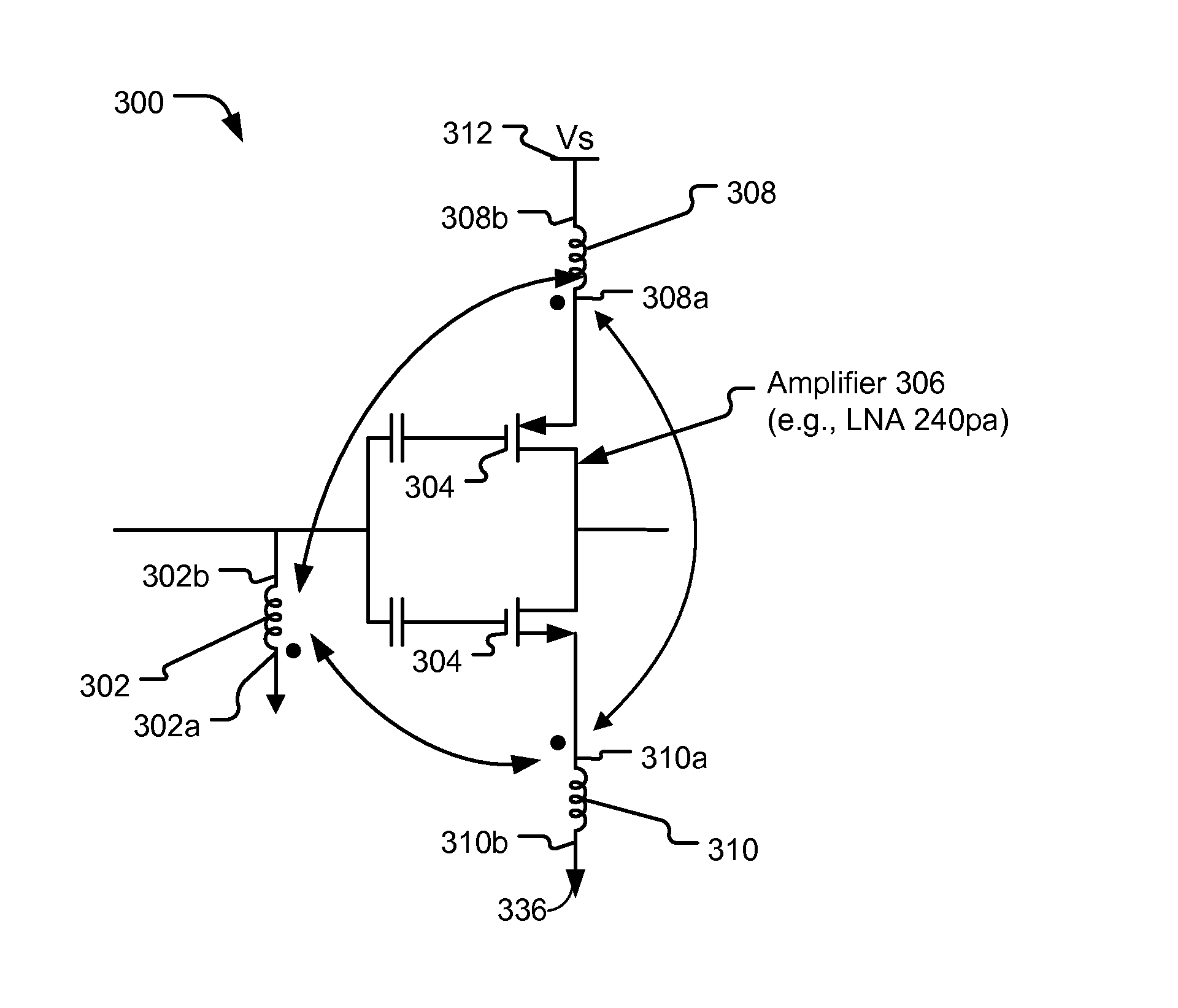
exemplary embodiment 300
[0024]FIG. 3 illustrates an exemplary embodiment 300 of an amplifier 306 that is coupled to a triple-coupled arrangement of inductors. The amplifier 306 may be coupled to a first inductor, illustrated as a shunt inductor 302, a second inductor 308, and a third inductor 310. The shunt inductor 302 is coupled to an input of the amplifier 306 (e.g., coupled to gates 304 of an inverter-type LNA). A first terminal 302a of the shunt inductor 302 is connected to ground, and a second terminal 302b of the shunt inductor 302 is coupled to the input of the first amplifier 306. The shunt inductor 302 is inductively coupled to the second inductor 308, having terminals 308a and 308b coupled as shown, and to the third inductor 310, having terminals 310a and 310b coupled as shown. In an illustrative example, the inductors 308, 310 are degenerative inductors of a degeneration transformer as depicted in FIG. 3. The inductor 308 couples the first amplifier 306 to a first supply node 312 (e.g., a volta...
exemplary embodiment 500
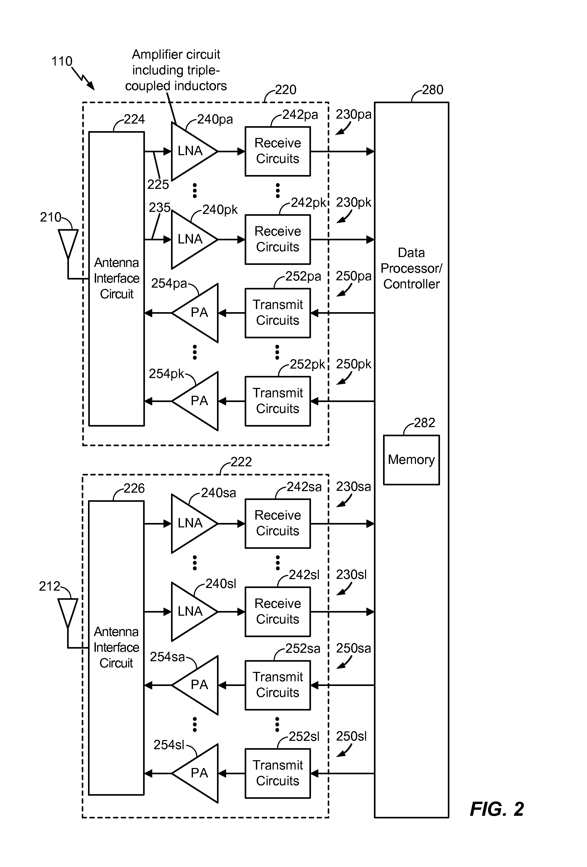
[0026]FIG. 5 illustrates an exemplary embodiment 500 of circuitry that includes the amplifier 306 and a second amplifier 316, each of which is coupled to a respective triple-coupled arrangement of inductors. A first switch 320 selectively couples an input node 390 (e.g., a node internal to the antenna interface circuit 224 of FIG. 2) via the first input signal path 225 to an input of the first amplifier 306. A second switch 322 selectively couples the input node 390 to an input of the second amplifier 316. An output 330 of the first amplifier 306 is coupled to a first receiver circuit that includes a first transformer 332 and a first mixer 334. An output 340 of the second amplifier 316 is coupled to a second receiver circuit that includes a second transformer 342 and a second mixer 344. The first amplifier 306 and the first receiver circuit may correspond to the LNA 240pa and the receiver circuit 242pa of FIG. 2, respectively, and the second amplifier 316 and the second receiver cir...
exemplary embodiment 600
[0036]FIG. 6 illustrates an exemplary embodiment 600 of the amplifiers 306, 316 of FIG. 5 using series-coupled inductors 602, 652 in place of the shunt inductors 302, 352 of FIG. 5. The first switch 320 selectively couples the input node 390 via the first input signal path 225 to a first terminal (e.g., a positive terminal) of a first series-coupled inductor 602 to receive an input signal. A second terminal (e.g., a negative terminal) of the first series-coupled inductor 602 is coupled to an input of the first amplifier 306. The second switch 322 selectively couples the input node 390 via the second input signal path 235 to a first terminal of a second series-coupled inductor 652. A second terminal of the second series-coupled inductor 652 is coupled to the input of the second amplifier 316. The output 330 of the first amplifier 306 is coupled to the first receiver circuit that includes the first transformer 332 and the first mixer 334. The output 340 of the second amplifier 316 is ...
PUM
 Abstract
Description
Claims
Application Information